Table of Contents
How to customize the Ambarella firmware of the SJCAM SJ8 Pro
See also my other pages about the SJCAM SJ8 Pro action camera: SJCAM SJ8 Pro Review, SJCAM SJ8 Pro WiFi Ambarella API and SJCAM SJ8 Pro Custom Firmware.
In this page there are some notes about customizing the firmware of the SJCAM SJ8 Pro action camera, using the BitrateEditor software. BitrateEditor is not just about bitrates, it can also change firmware tables about gamma values, YUV values, exposure and many others.
On many cameras based on the Ambarella SoC (but also Novatek based cameras have this opportunity) it is possible to tweak the firmware changing specific values and tables, to customize several parameters: bitrates, YUV settings, gamma correction, chroma correction, 3D-LUT tables, etc. There is an active community of hackers which produces modded firmwares that you can flash on the camera, generally using the official upgrade procedure. Each firmware is specific for a make/model, it is based on a specific released official version and it contains the necessary poke(s) directly into the binary file. Generally the source code of the firmware is not available, either documentation about features and data structure is missing, so the big work is done by reverse engeneering and countless trials.
Unfortunately it seems that the hackers community is very jealous of their findings, hardly anyone writes complete documentation and it seems that the main interest is to prove our own supremacy by publishing as many mods as possible, without documenting exactly what was done inside. A notable exception is the BitrateEditor software by V_Max hacker; being released as open source it is a source of very useful information on the internal structure of firmware files.
Anatomy of the Ambarella firmware
We used firmware 1.3.2 released in date 2020-06-08. Using a Python script which I wrote (see ambarella-h22-firmware-tools), it is possible to inspect the content of the firmware file SJ8_FWUPDATE.bin; it contains the following sections:
| SJ8 Pro 1.3.2 Firmware File Header - Sections Table | ||||
|---|---|---|---|---|
| Len (+header) | ~CRC32 | Running CRC32 | Offset | Content |
| 26095616 | 0xE1744B4A | 0xE1744B4A OK | 0x00000230 | RTOS image flashed into mtdblock1. |
| 3541248 | 0xB6201EA3 | 0xB6201EA3 OK | 0x018E3230 | ROMFS flashed into mtdblock2. |
| 5366016 | 0x9A1E6759 | 0x9A1E6759 OK | 0x01C43B30 | ROMFS flashed into mtdblock3. |
| 6590728 | 0x4898C473 | 0x4898C473 OK | 0x02161C30 | Linux kernel flashed into mtdblock4. |
| 10699008 | 0x8CC124AC | 0x8CC124AC OK | 0x027AAD38 | GNU/Linux Squashfs filesystem flashed into mtdblock5. |
| Ambarella Firmware Sections found by Magic 90EB24A3 | |||||||
|---|---|---|---|---|---|---|---|
| Header | Section | Len | CRC32 | Version | Date | Memory | Flag |
| 0x00000230 | 0x00000330 | 26095360 | 0xF42BD26A OK | 0.1 | 2020-06-08 | 0x00020000 | 0x31C5E000 |
| 0x018E3230 | 0x018E3330 | 3540992 | 0xCB683D41 OK | 0.1 | 2020-05-12 | 0x00000000 | 0x06C10000 |
| 0x01C43B30 | 0x01C43C30 | 5365760 | 0x45520C76 OK | 0.1 | 2020-05-12 | 0x00000000 | 0x0A3C0000 |
| 0x02161C30 | 0x02161D30 | 6590472 | 0xEB6ACD7A OK | 0.1 | 2020-05-12 | 0x3A680000 | 0x00000000 |
| 0x027AAD38 | 0x027AAE38 | 10698752 | 0x5686EF50 OK | 0.1 | 2020-05-12 | 0x00000000 | 0x00000000 |
Refer to the comments contained into the ambarella-h22-firmware-unpack script for a first analysis of file structure.
Bitrate and GOP
It is possible to customize bitrates and GOP values for all video modes. Launch the SJ8Pro.bitrates.bat script:
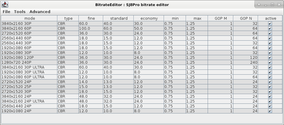
The SJCAM SJ8 Pro camera has very high default values for the Group of pictures, i.e. the recorded videos have only one keyframe per second. This is bad when you want to cut videos on sub-second boundaries without re-encoding the stream. I rather prefer 4 keyframes per second: at 30 FPS this means a value of 8 for GOP-N.
Changes will be written into firmware section #1 (the RTOS image). The GOP table is found using a magic string at offset 0x0188A880, the actual table is layed-out starting from offset 0x0188A8C0 and consits of 86 rows, each containing four 32bits values:
| Offset | Content | Notes |
|---|---|---|
| 0x0188A880 | 0xE9030000 0xC05D0000 - 0x01000000 0x000AA005 0x000AA005 0x0910 | Magic string |
| … | ||
| 0x0188A8C0 | 0x01000000 0x20000000 0x20000000 0x00000000 | First GOP M / GOP N value |
| … | ||
| 0x0188AE10 | 0x01000000 0x18000000 0x18000000 0x000F7008 | Last GOP M / GOP N value |
YUV profiles
YUV profiles are applied probably very early into the video processing pipeline by the Ambarella processor. They can alter the color space of the images by acting on the luma (the overall brightness) and the chrominance (the colors); a YUV profile defines some mathematic rules to alter luma and chrominance to satisfy particular needs.
The SJ8 Pro firmware contains 28 YUV prfiles, they are stored inside the files de_default_still_Imx377 and de_default_video_Imx377 contained into section #3 (the ROMFS section at firmware file offset 0x01C43C30). BitrateEditor can show all of them launching the SJ8Pro.yuv.all.profiles.bat script:

Only four profiles from the above are actually used: Video VIVID, Video FLAT, Photo VIVID and Photo FLAT. There are also two additional profiles hard coded into the section #1 (the RTOS image), which are used by default at power-on: Video default and Photo default. You can launch the SJ8Pro.yuv.bat script to see all of them:


Each profile consists of six values because there are two parameters for each component Y, U and V. The numbers define a linear transformation: the first one is the multiplier (the slope of the linear equation), the second number is the offset (the y-intercept of the line). The multiplier is intended to be divided by 1024, so a value of 1024 means actually 1024 / 1024 = 1 (i.e. no changes on the raw value).
| Value | Range | Notes |
|---|---|---|
| Y | 0 ÷ 2048 | Multiplier for the luma signal, i.e. the brightness of the image. |
| U | 0 ÷ 2048 | Multiplier for the blue projection (blue - luma). |
| V | 0 ÷ 2048 | Multiplier for the red projection (red - luma). |
| Y-offset | -128 ÷ 127 | Shift brightness from black to white. |
| U-offset | -128 ÷ 127 | Shift colors from yellow to blue. |
| V-offset | -128 ÷ 127 | Shift colors from green to red. |
For the multiplier: a value of 0 means a zero multiplier (horizonatl slope), 1024 means 1.0 (neutral multiplier), a value of 2048 means 2.0 multiplier.
For the offset shift: a value of -128 means -50% of the full range, a value of +127 means +50% of the full range.
Values for Y, U and V are unsigned integers in the range 0 ÷ 2048, values for Y-offset, U-offset and V-offset are signed integers in the range -128 ÷ +127. Each YUV profile occupies 24 bytes into the file.
| File de_default_video_Imx377 | ||
|---|---|---|
| Profile Video VIVID | ||
| Offset | Value | Data Type |
| 0x26 | Y | 2 bytes unsigned integer |
| 0x28 | ??? | 6 bytes * 0x00 |
| 0x2E | U | 2 bytes unsigned integer |
| 0x30 | ??? | 6 bytes * 0x00 |
| 0x36 | V | 2 bytes unsigned integer |
| 0x38 | Y-offset | 2 bytes signed integer (2-complement) |
| 0x3A | U-offset | 2 bytes signed integer (2-complement) |
| 0x3C | V-offset | 2 bytes signed integer (2-complement) |
| Profile Video FLAT | ||
| Offset | Value | Data Type |
| 0xA2 | Y | 2 bytes unsigned integer |
| 0xA4 | ??? | 6 bytes * 0x00 |
| 0xAA | U | 2 bytes unsigned integer |
| 0xAC | ??? | 6 bytes * 0x00 |
| 0xB2 | V | 2 bytes unsigned integer |
| 0xB4 | Y-offset | 2 bytes signed integer (2-complement) |
| 0xB6 | U-offset | 2 bytes signed integer (2-complement) |
| 0xB8 | V-offset | 2 bytes signed integer (2-complement) |
As stated above, changes will be written by BitrateEditor into sections #3 (the ROMFS section at offset 0x01C43C30), inside the files de_default_still_Imx377 and de_default_video_Imx377. Instead the default video profiles are hard-coded into section #1 (the RTOS image); firmware 1.3.2 has the profiles hard-coded at offset 0x18D3C8A and 0x18D3F72 relative to the section begin.
Using ImageMagick to preview a YUV profile
You may want to experiment with YUV values to obtain a specific image result, but surely you don't want to flash a new firmware on each try! You can use ImageMagick to preview the YUV transformation on a single frame recorded with a neutral setting (1024 as the multiplers and 0 as the offsets).
With the following shell script (tested with ImageMagick 6.9 on GNU/Linux) it is possible to preview a new YUV from an image acquired with neutral settings. Input values are in the range [0, 2048] for the multipliers and in the range [-128, 127] for the offsets, as expected by BitrateEditor. Such values will be converted for use by ImageMagick to the ranges [0, 2.0] and [-0.5, 0.5] respectively.
#!/bin/sh
# Get filename from command line.
FILENAME="$1"
# Range: [0, 2048]
cY='980'
cU='1008'
cV='1008'
# Range [-128, 127]
oY='+6'
oU='+0'
oV='+0'
# Remove extension from filename.
BASENAME="$(echo "$FILENAME" | sed 's/\.jpg$//' | sed 's/\.png$//' )"
# Function to do floating point calculations.
calc() { awk "BEGIN{print $*}"; }
# Convert YUV coefficients to the range [0.0, 2.0]
cY="$(calc $cY/1024)"
cU="$(calc $cU/1024)"
cV="$(calc $cV/1024)"
# Convert YUV offsets to the range [-0.5, 0.5]
oY="$(calc $oY/256)"
oU="$(calc $oU/256)"
oV="$(calc $oV/256)"

# Use ImageMagick internal conversion from/to YCbCr and sRGB.
convert "$FILENAME" \
    -colorspace 'YCbCr' -separate \
    \( -clone 0 -fx "      $oY + $cY * u[0]"         -clamp \) \
    \( -clone 1 -fx "0.5 + $oU + $cU * (u[0] - 0.5)" -clamp \) \
    \( -clone 2 -fx "0.5 + $oV + $cV * (u[0] - 0.5)" -clamp \) \
    -delete 0-2 \
    -set colorspace 'YCbCr' -combine -colorspace sRGB "${BASENAME}_custom.jpg"
The ImageMagick incantation is explained here:
- The first line does the conversion from sRGB to the YCbCr colorspace (when dealing with digital images, if you read YUV, it is actually YCbCr). The result are three separated channels: Y, Cb and Cr, numbered #0, #1 and #2.
- The second line makes a clone of the Y channel and applies the multiplier and the offset. A new channel will be created, with number #3.
- The third and fourth lines will create the modified versions of channels Cb and Cr, applying the corrections. Two new channels will be created: #4 and #5.
- Using the delete command, the first three channels will be deleted, so only the modified ones remain.
- The three modified Y, Cb and Cr channels are combined together and converted back to sRGB.
NOTICE: BitrateEditor shows a preview of an image simulating the selected YUV profile. The program uses some hard-coded coefficients to perform the conversion from/to YCbCr and RGB. There is not a single formula for such a conversion, but there are many standards (BT.601, BT.709, JPEG) adopted in various circumstances (analog, digital, HDTV, etc.). In the script above we did not use any of that formulas, but instead we relayed on the internal method used by ImageMagick, we just used the name of the colorspace YCbCr.
Exposition (Metering Mode)
The SJ8Pro contains three metering tables used for the three metering modes: Center, Spot and Average. Each table is a matrix of 12×8 integers; each number indicates the weight of that portion of the image in calculating the correct auto exposure.
By inspecting the exposition matrices with BitrateEditor, it seems that they are actually messed-up: Spot and Average seems to be swapped:
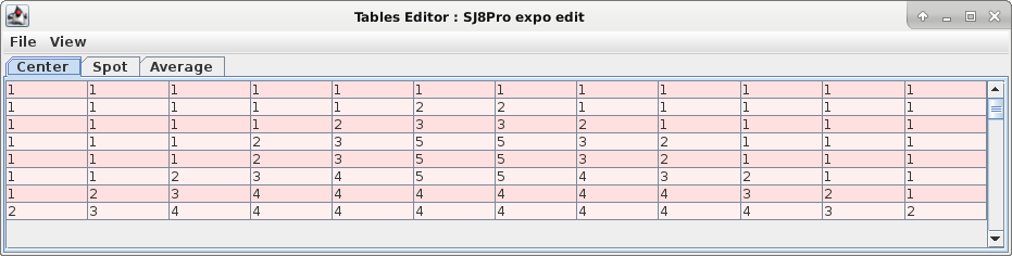
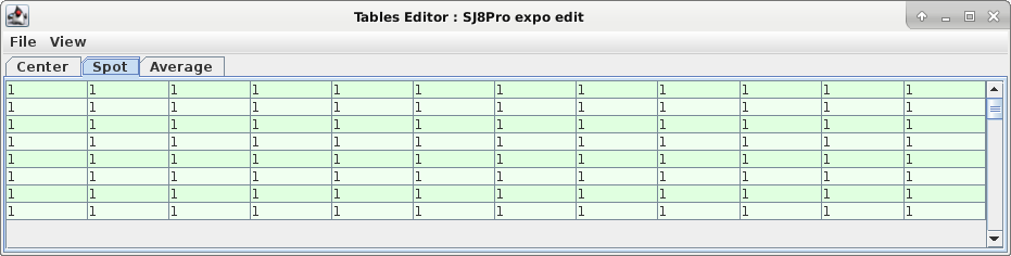
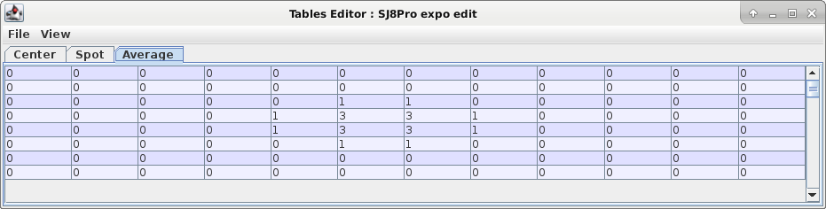
The tables are contained into the aaa_default_00_Imx377 file (inside the ROMFS section #3), at offsets 0x285, 0x2E5 and 0x345 respectively. Each exposition table is a matrix of 12×8 bytes; each number represents the exposition weight of a portion of the image, being the image divided in 8 rows and 12 columns.
Gamma curves
Simply speaking, gamma can make the image lighter or darker in a selective manner, i.e. acting differently on shadows and highlights. By acting differently on the red, green and blue channels, gamma can also do color balancing.
Gamma correction is probably applied in a later stage of the Ambarella video processing pipeline. Gamma is a function that transforms brightness or luminance values, it is usually nonlinear and affects the highlights, midtones, and shadows separately. In our case there are different gamma curves for the three color channles: red, green and blue. Different video formats (4K, 1080, etc) use different gamma correction tables.
BitrateEditor exposes and allow the modification of several look-up tables (LUT) contained into the files adj_video_default_0[0-5]_Imx377 and adj_still_default_0[0-1]_Imx377 (file are contained into firmware section #3). The tables are shown grouped by three, i.e. we work actually on a 3 x 1D-LUT, one for each color channel: Red, Green and Blue.
For each color component we have 256 values arranged for compactness in 16 rows. Each value is likely a 10 bit integer, BitrateEditor allows you to enter a number ranging from 0 to 1024, but I strictly adivse to remain into the range [0, 1023].
In the following picture we see the editing of the group called 4K30/255;
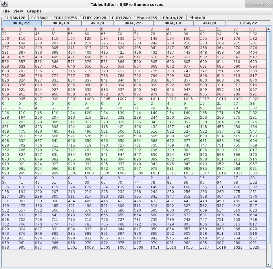
The LUTs are used to transform each color component, mapping 254 input values into a 10-bits integer. For example, following the table above, a red input value of 0 is mapped to 0 (first entry of the red table), a red input value of 16 is mapped to 37 (seventeenth entry of the red table), and so on. The 256 values will be used probably with spline interpolation to calculate the transformation on each color component.
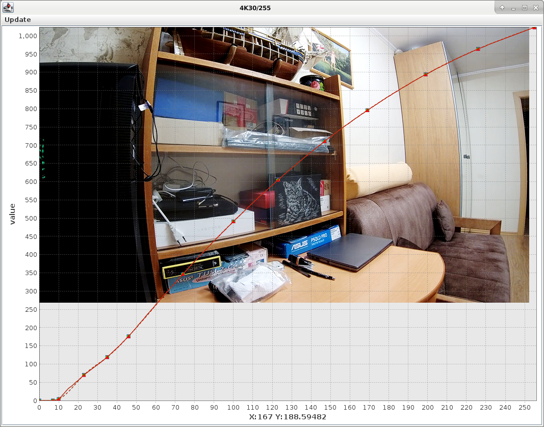
Instead of writing down the raw numeric values, BitrateEditor allow you to draw the gamma curves just dragging nodes over a graph (select the Graphs menu). In real time you will see how the curves will impact over the image colors. Once you are satisfied with the curves. select the Update table from spline from the menu, this will update numeric values into the table. Otherwise select Recalculate spline to re-draw the curves from table numbers. Use right click on the nodes to view the useful context menu.
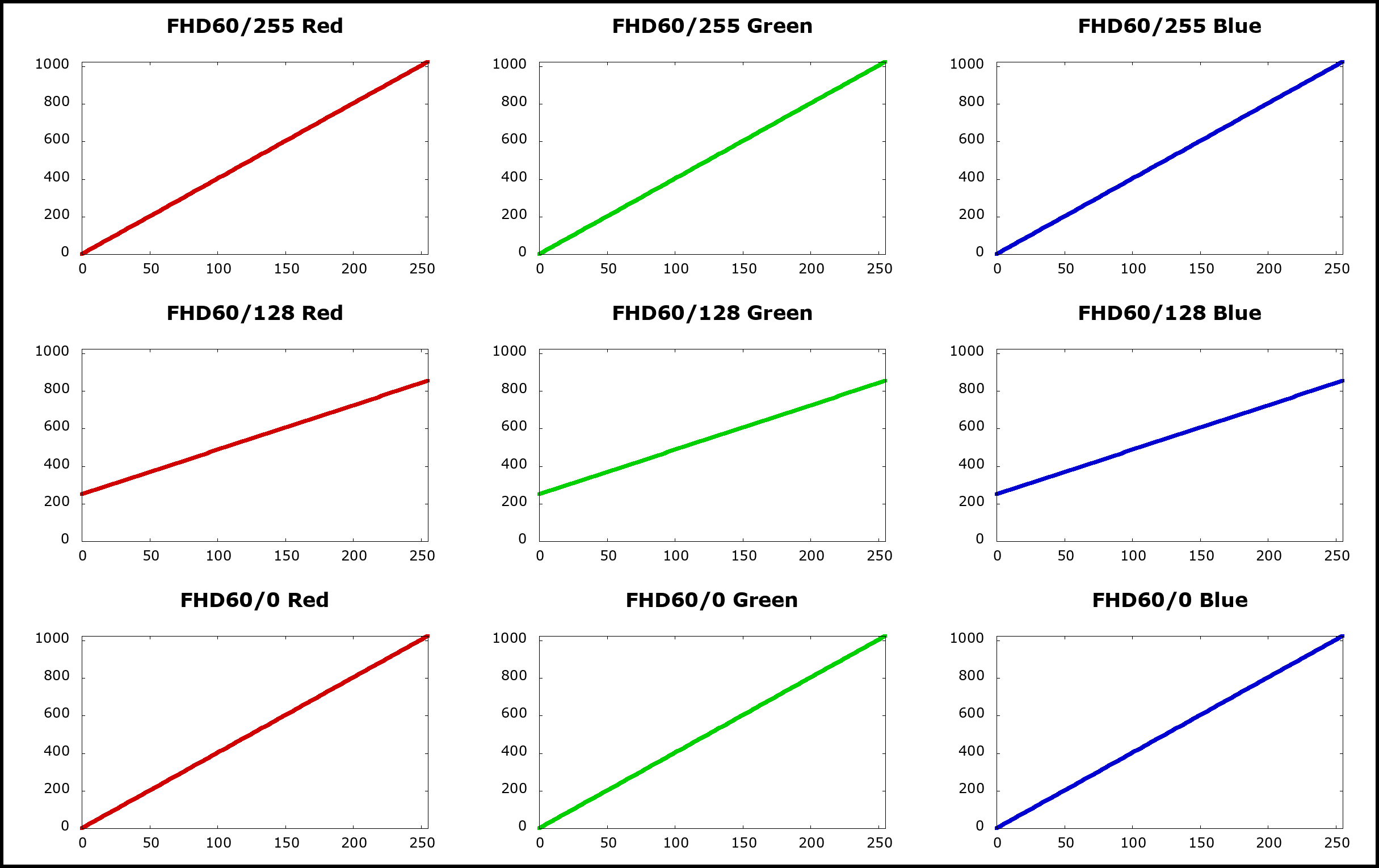
What gamma curves are applied on each video mode
In the image processing pipeline, the SJ8 Pro actually uses two groups of three LUTs. For example, if you are filming at 4K30 FPS, the groups used are 4K30/255 and 4K30/128. The groups are applied to each frame using an unknown method, it seems that the first group */255 applies to highlights, the second group */128 applies to shadows, while it seems that the */0 group is not used at all. See below for a partial study on how gamma tables are mixed together.
The following table shows what group of LUT tables are used for each video mode. Also the tables used for photo modes are listed:
| Group | Contained in file | Used for video modes |
|---|---|---|
| 4K30/* | adj_video_default_00_Imx377 | 4K@(25,30) |
| 4K60/* | adj_video_default_01_Imx377 | 4K@(50,60) |
| FHD60/* | adj_video_default_02_Imx377 | 4K@24, 4K-Ultra@(24,30) 2720×1520@(24,25,30,50,60) 2560×1440@(24,25,30,50,60) 1920×1080@(24,25,30,50,60) 1920×1080-Ultra@(30,60) Touchscreen operations |
| FHD120/* | adj_video_default_03_Imx377 | 1920×1080@120 |
| 720@240/* | adj_video_default_04_Imx377 | 1280×720@240 |
| 4K30Gyro/* | adj_video_default_05_Imx377 | 4K@(25,30) with Gyro Stabilizer |
| Group | Contained in file | Used for photo mode/ISO |
| Photo/* | adj_still_default_00_Imx377 | Photo 100,200,400 Burst Mode 100,200,400,800,1600,3200,6400 Photo Lapse 100,200,400 |
| Photo-Hi-ISO/* | adj_hiso_still_default_00_Imx377 | Photo 800,1600,3200,6400 Photo Lapse 800,1600,3200,6400 |
It seems rather crazy, but the tables contained into adj_video_default_05_Imx377 are used only when Gyro Stabilizer is enabled and mode is 4K at 25 or 30 fps.
How gamma curves are mixed together
I tried to understand how the gamma curves are mixed together to produce the final result. As far I know, there is not official documentation from Ambarella and there is no exhaustive treatment of the subject. I proceeded by uploading some gamma curves with a very specific pattern, then I filmed with the camera a reference image displayed on a computer display, trying to keep always the same lighting conditions and changing the ISO and EV (exposition) settings.
The fixed ISO modes work in a quite predictable manner, whereas ISO MAX modes are rather hard to understand.
- Using fixed ISO modes (from ISO 100 to ISO 1600) it seems that only the */255 LUTs group is used, the other groups */128 and */0 do not play any role in this modes.
- Using dynamic ISO modes (from ISO MAX 100 to ISO MAX 6400) it seems that */255 and */128 groups are used: the first for bright areas and the second for shadows. The */0 curves remain unused.
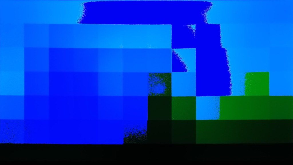
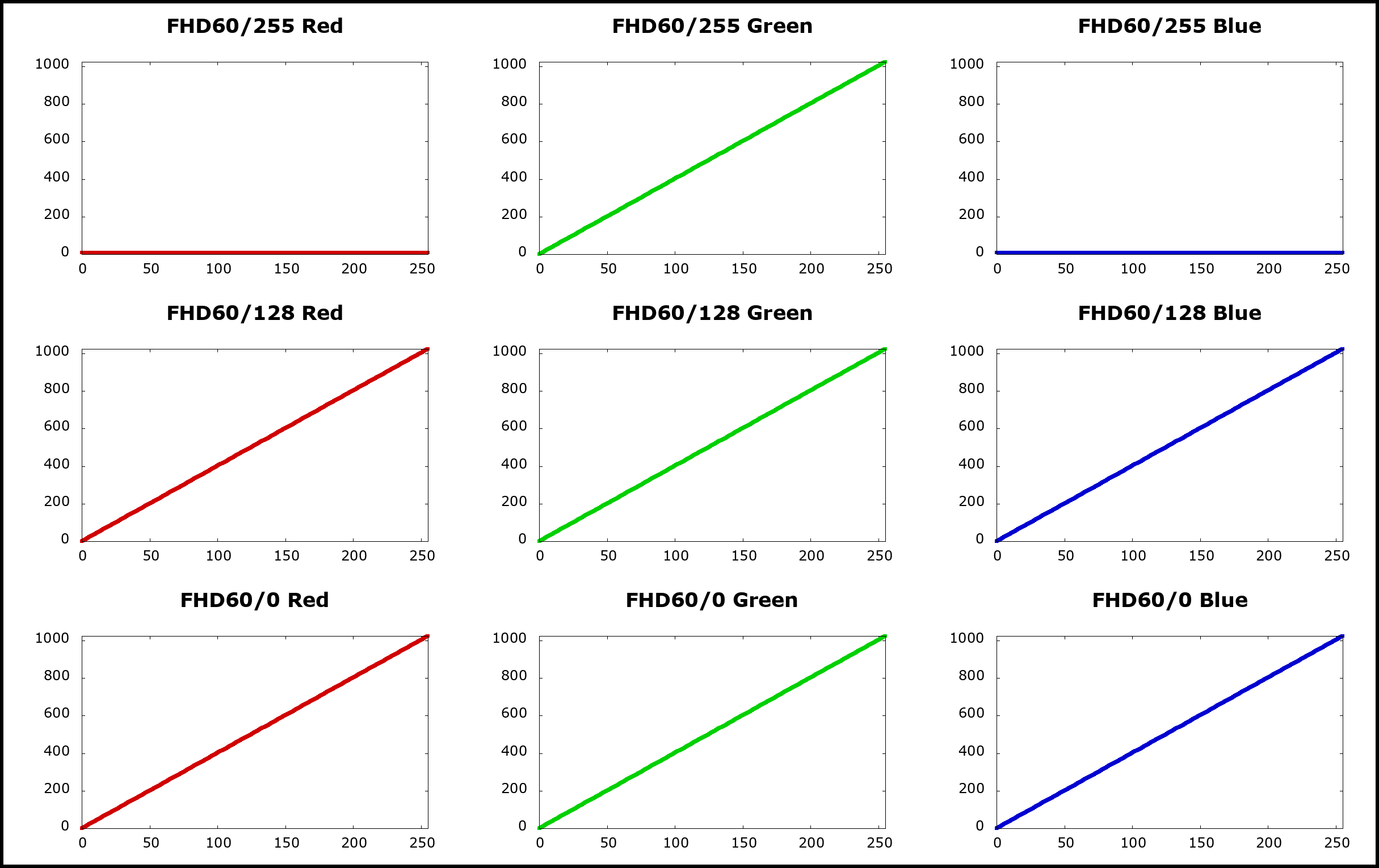
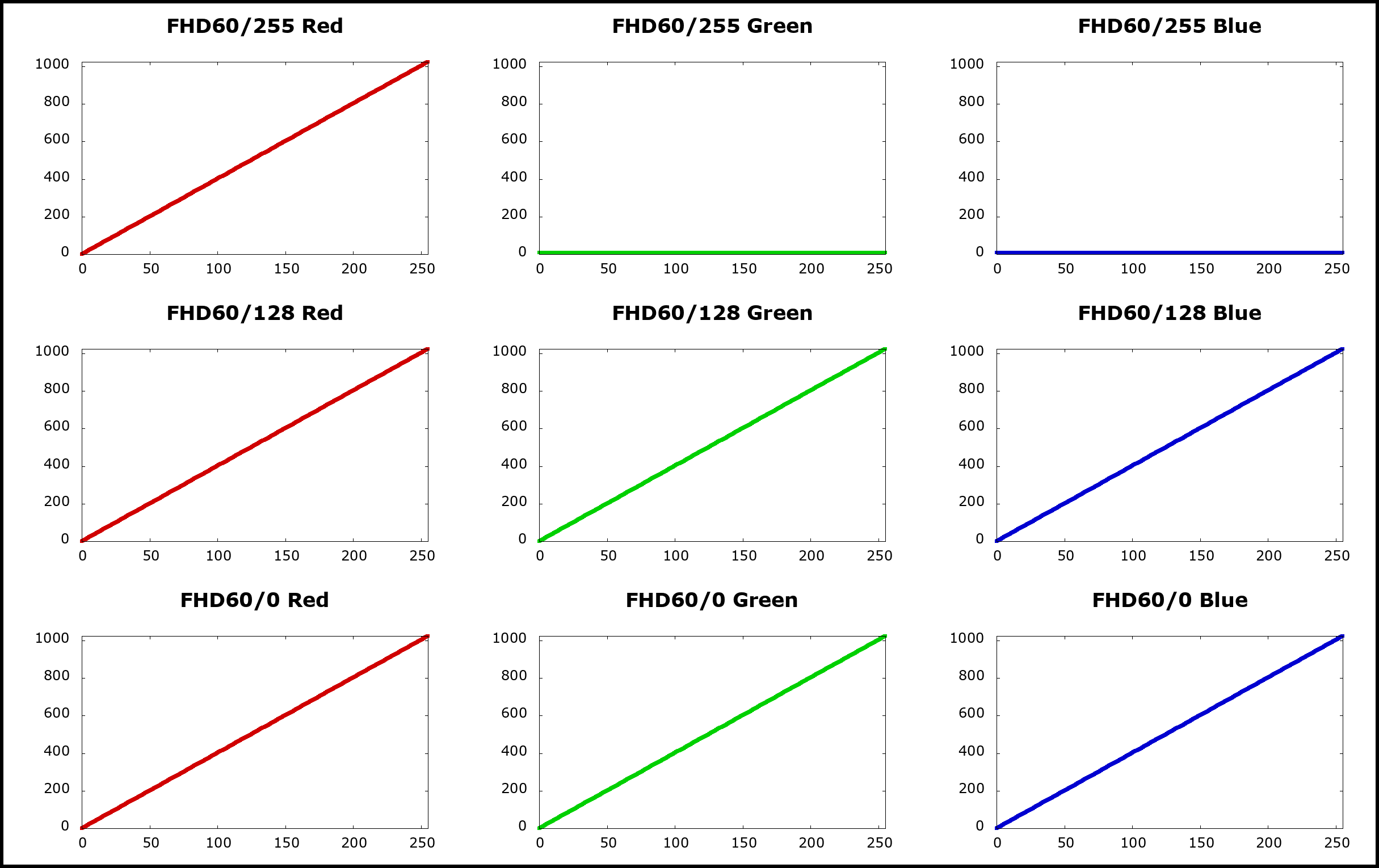
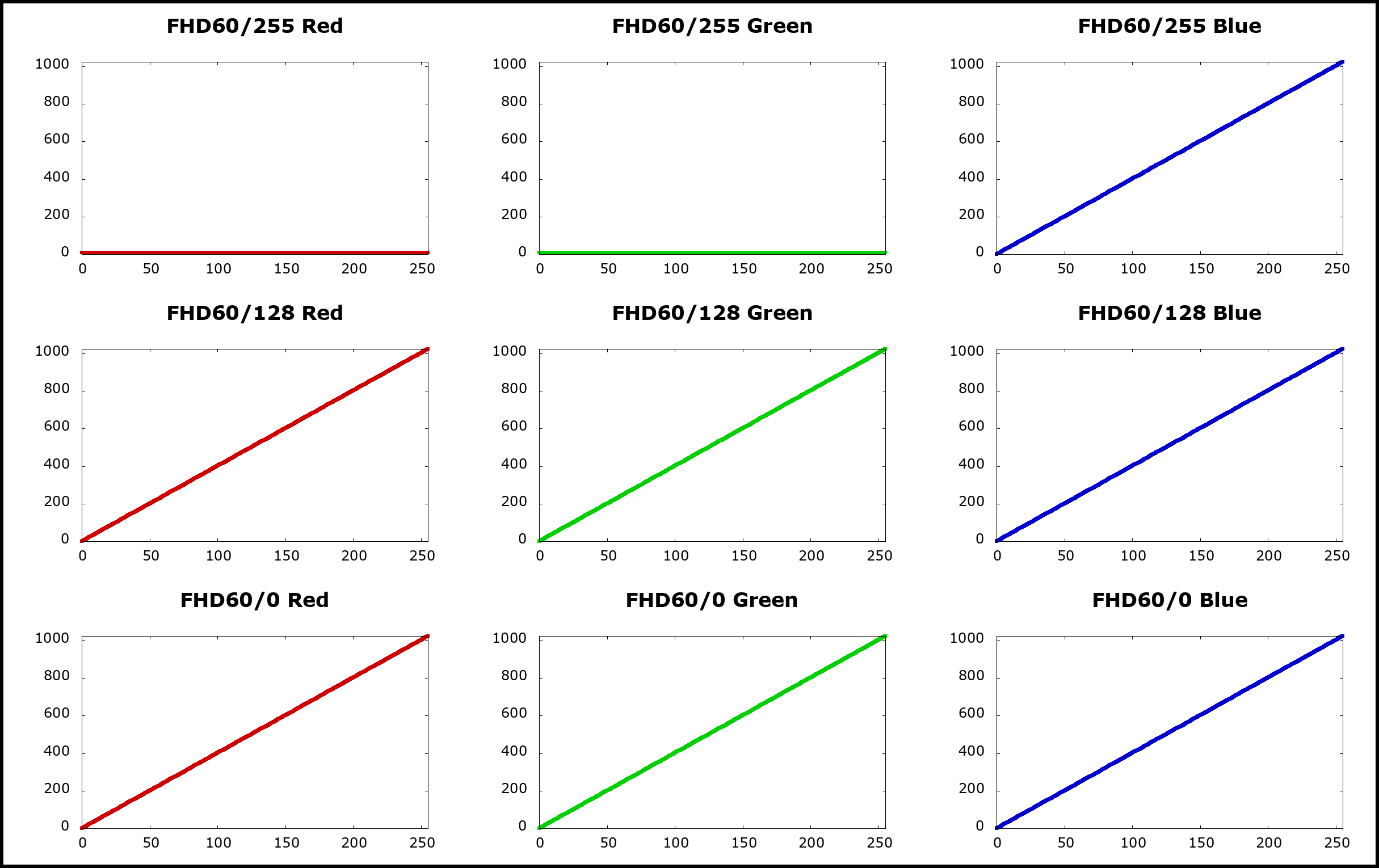
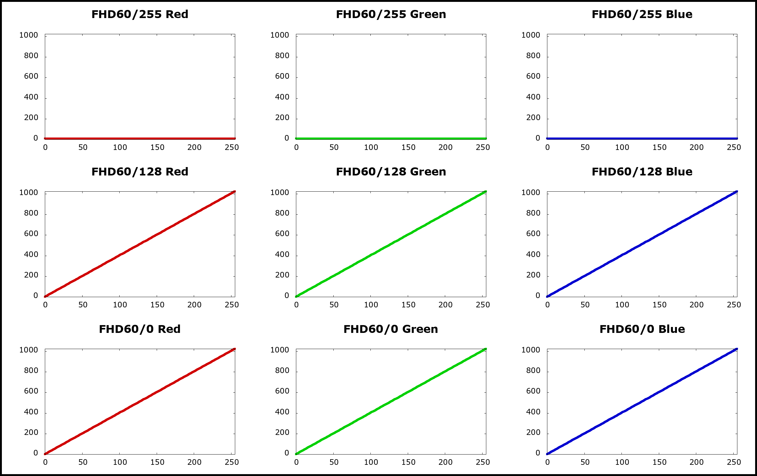
Fixed ISO 1600: test only one color per LUTs group
In the following two tests I set only one color channel for each LUTs group:
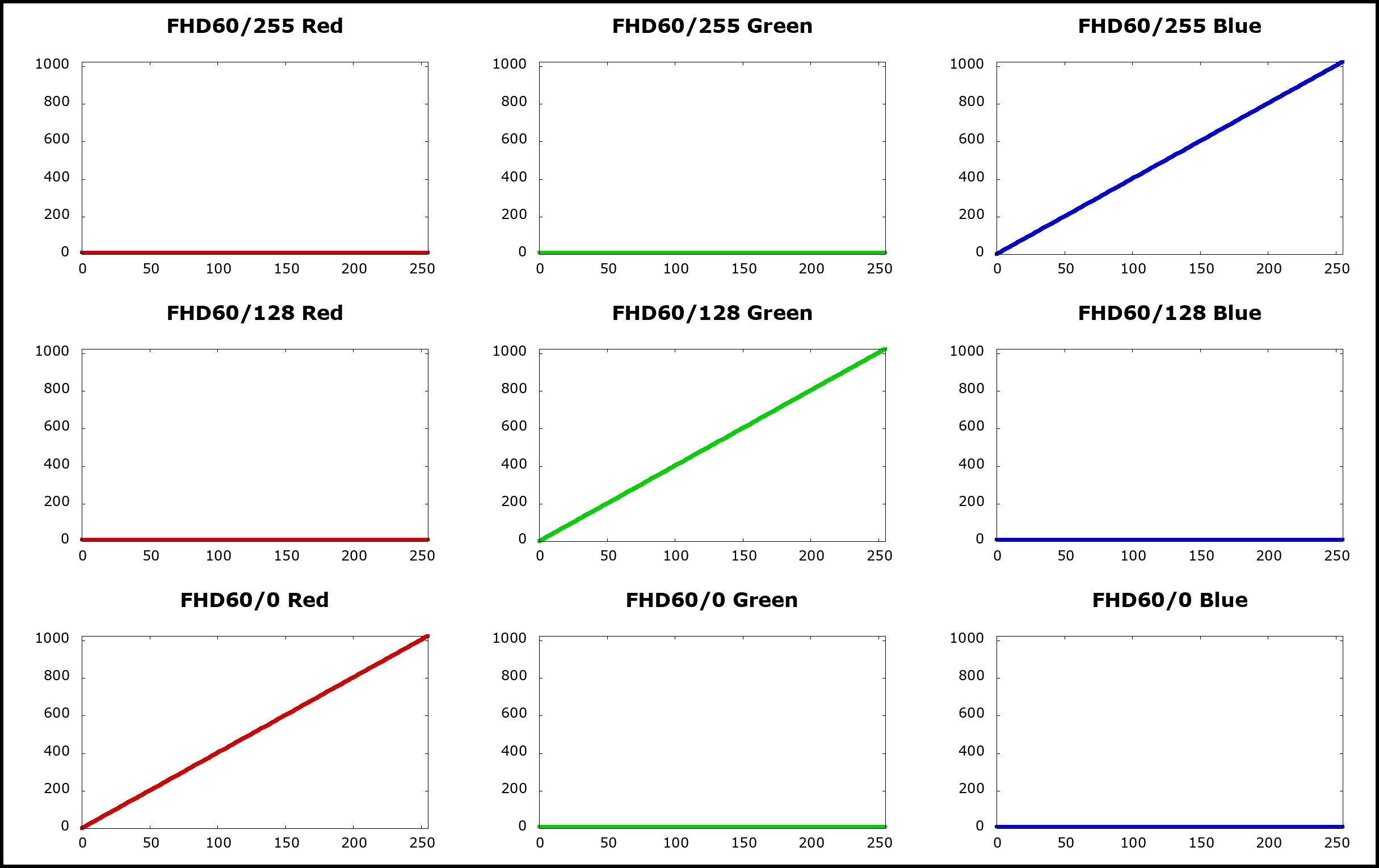
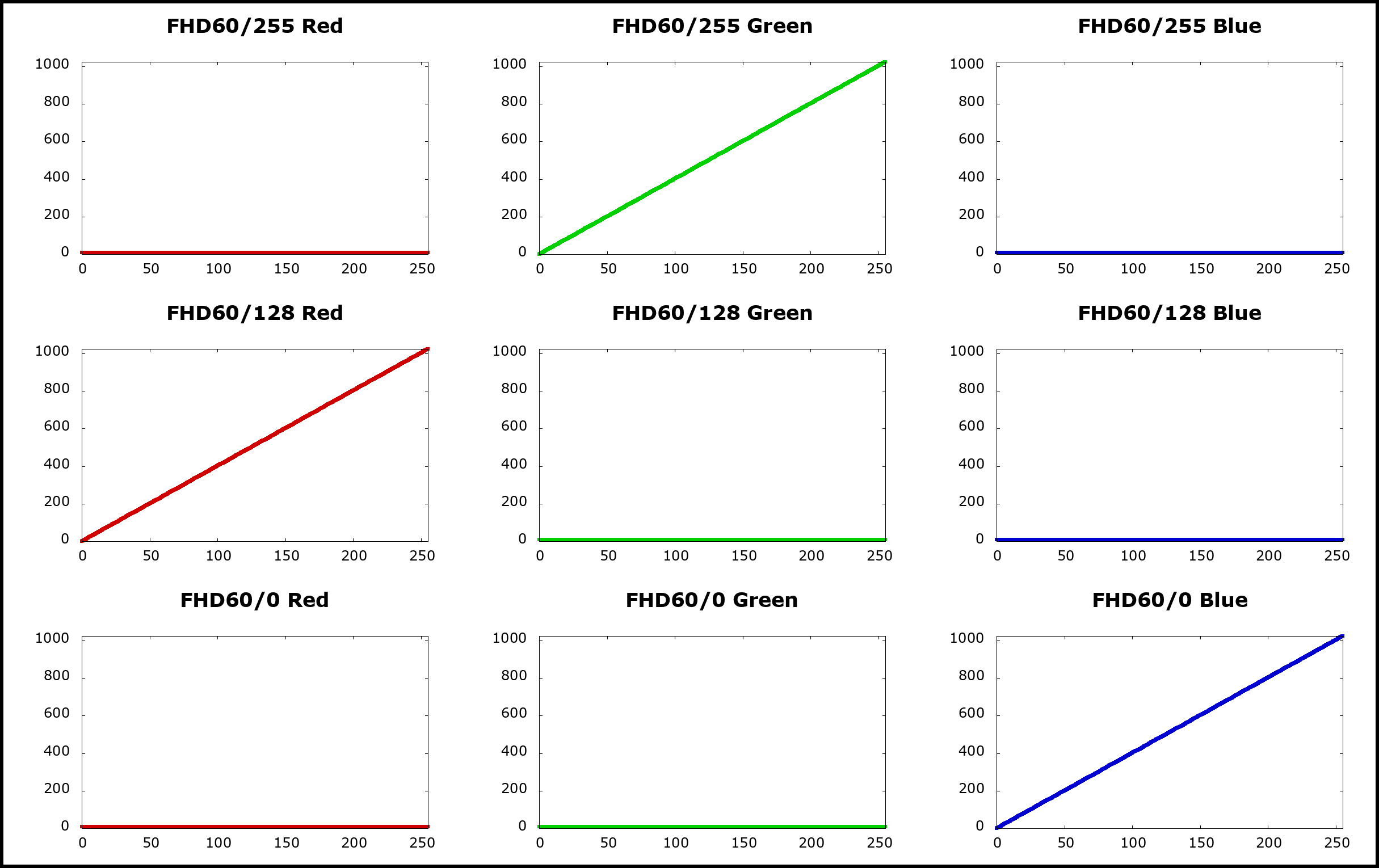
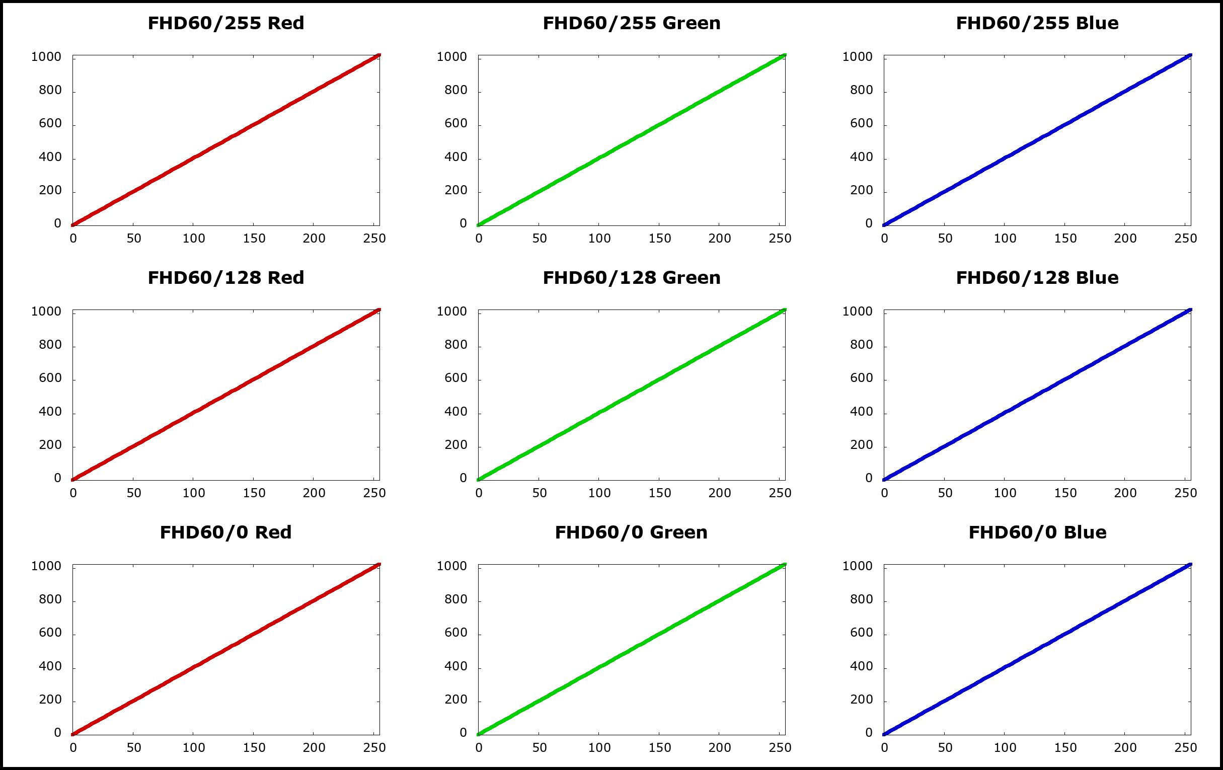
The following images were captured at ISO 1600 (using other fixed ISO modes produces similar results). The resulting frames show only the color enabled in the */255 group (blue in the first test, green in the second), so I deduced that LUTs group */128 and */0 are not used at all:

Fixed ISO 1600: only the */255 group matters
We made four other tests, mixing different slopes on LUT tables */255 and */128:

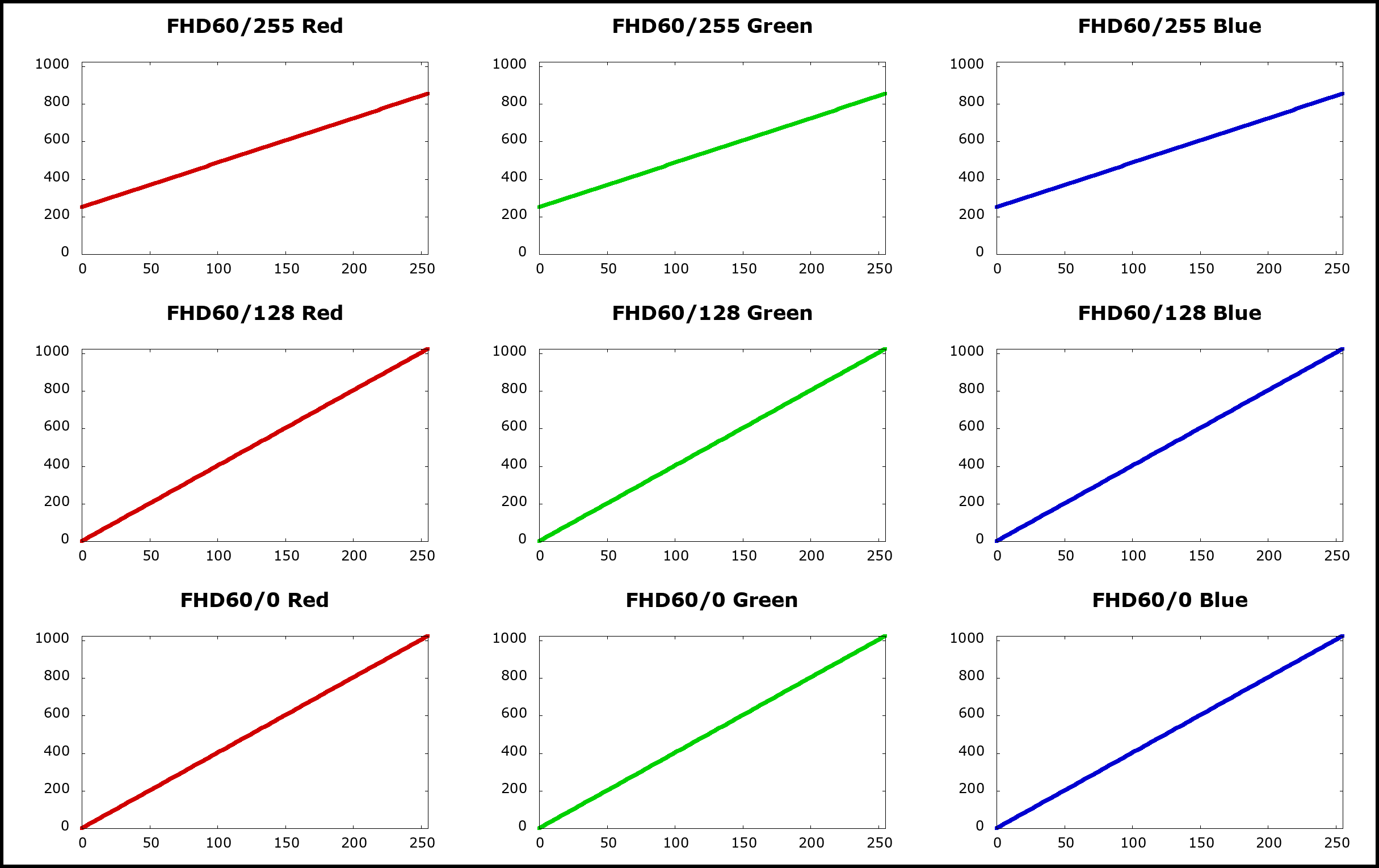
Even in these cases only the tables */255 produce effects on the final result. In first, second and fourth example the */128 gamma curves have a different slope (zero, 1 and 0.59), but no noticeable effects are visible in the images. In the third example the */255 gamma curves have a reduced slope, resulting into a visible reduced contrast.
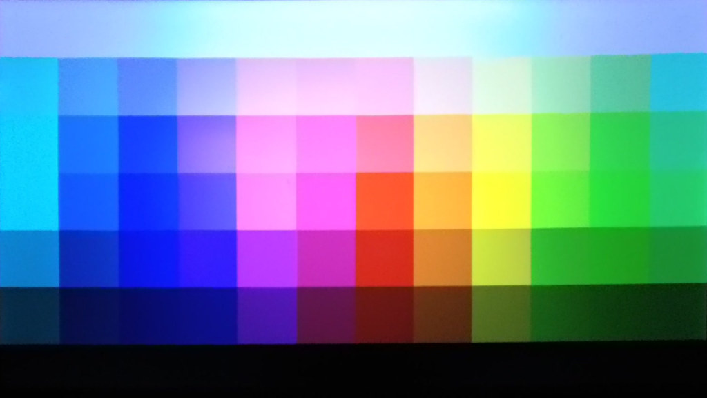
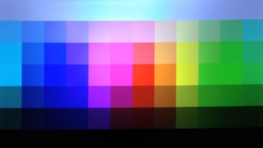
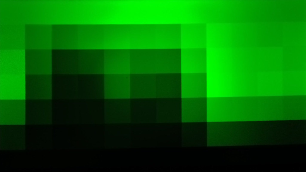
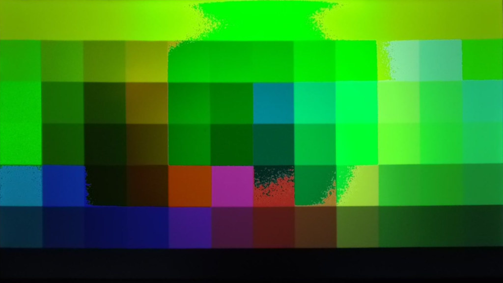
ISO MAX 6400: test only one color per LUTs group
Using ISO MAX modes, both the */255 and */128 groups become effective, whereas the */0 group still does not produce any visible effect.
The first two tests use gamma curves with only one different color component for each LUTs group (the same gamma graphs seen above):
- Test #28: blue for */255 group, green for */128 and red for */0.
- Test #29: green for */255 group, red for */128 and blue for */0.
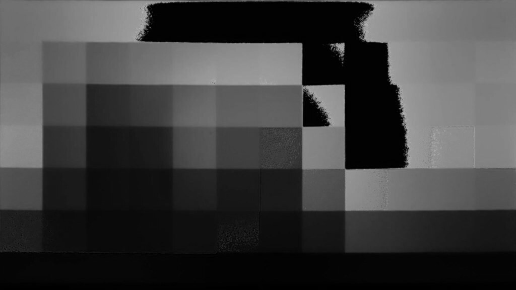
It is rather clear that the */255 group is used for the brightest part of the image, group */128 is used for the darker parts and the third color component from the */0 group is never used:
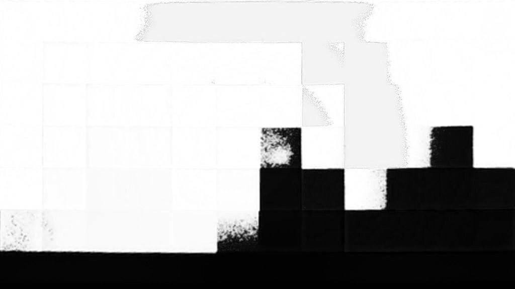
Separating the blue and the green components of the first test (produced by gamma curves */255 and */128 respectively), we get the following images. It seems that the curves are applied in a mutually exclusive manner: at some brightness threshold there is a cut-off and the color channel becomes zero (black), meaning that the relevant gamma curve does not apply anymore; it seems that there is no interpolation or bending between LUTs groups. Beside that, it is clear that gamma curve */128 produces halftones, whereas the curve */255 is applied augmenting by far the contrast, something like multiplying by 2 the gamma value:
Separating the green and the red components of the second test (produced by gamma curves */255 and */128 respectively) we can confirm the high contrast used in applying the */255 curve and the missing interpolation or blending of the two curves.

ISO MAX 6400: how does LUTs groups mixes
With the other four tests I tried to guess how the */255 and */128 LUTs are mixed together.

How does group */255 interpolate with */128?

- Below some brightness threshold, group */128 and */255 are used in combination. You can see the central part of the leftmost column, that is light blue, it is not rendered properly untill the */255 gives its contribute in blue channel.
- It seems that above some brightness threshold, there is a drastic change in gamma correction and group */255 becomes prevalent, if not exclusive.
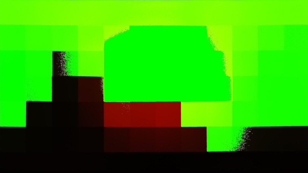
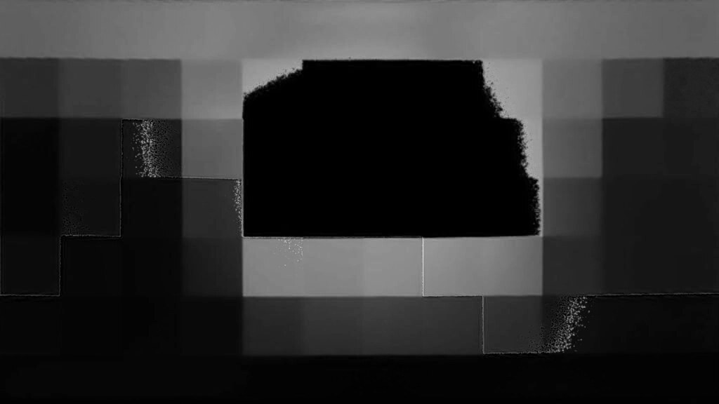
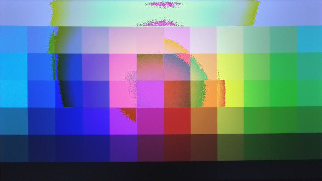
The following actual scene filmed wit test #38, shows that the brightest parts get a totally different gamma correction. However, it is not possible to explain why the color blue does not prevail in the brightest areas, as it should be the only color channel contributed by the */255 group. It seems that some other correction mechanism is applied when a color channel is too dark. I suppose that a negative linear green channel was automatically added:

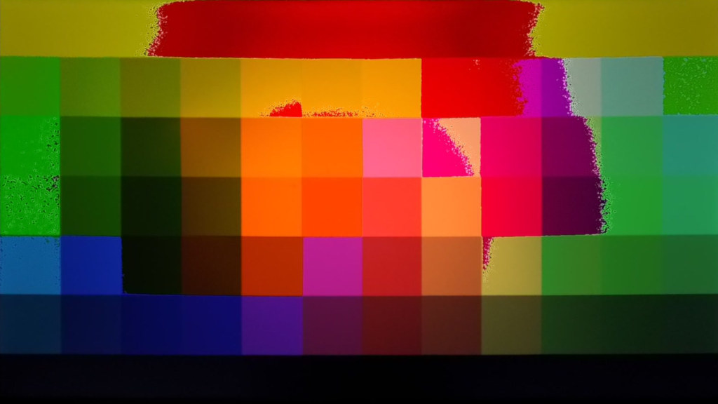
Anomalies if */255 is too dark
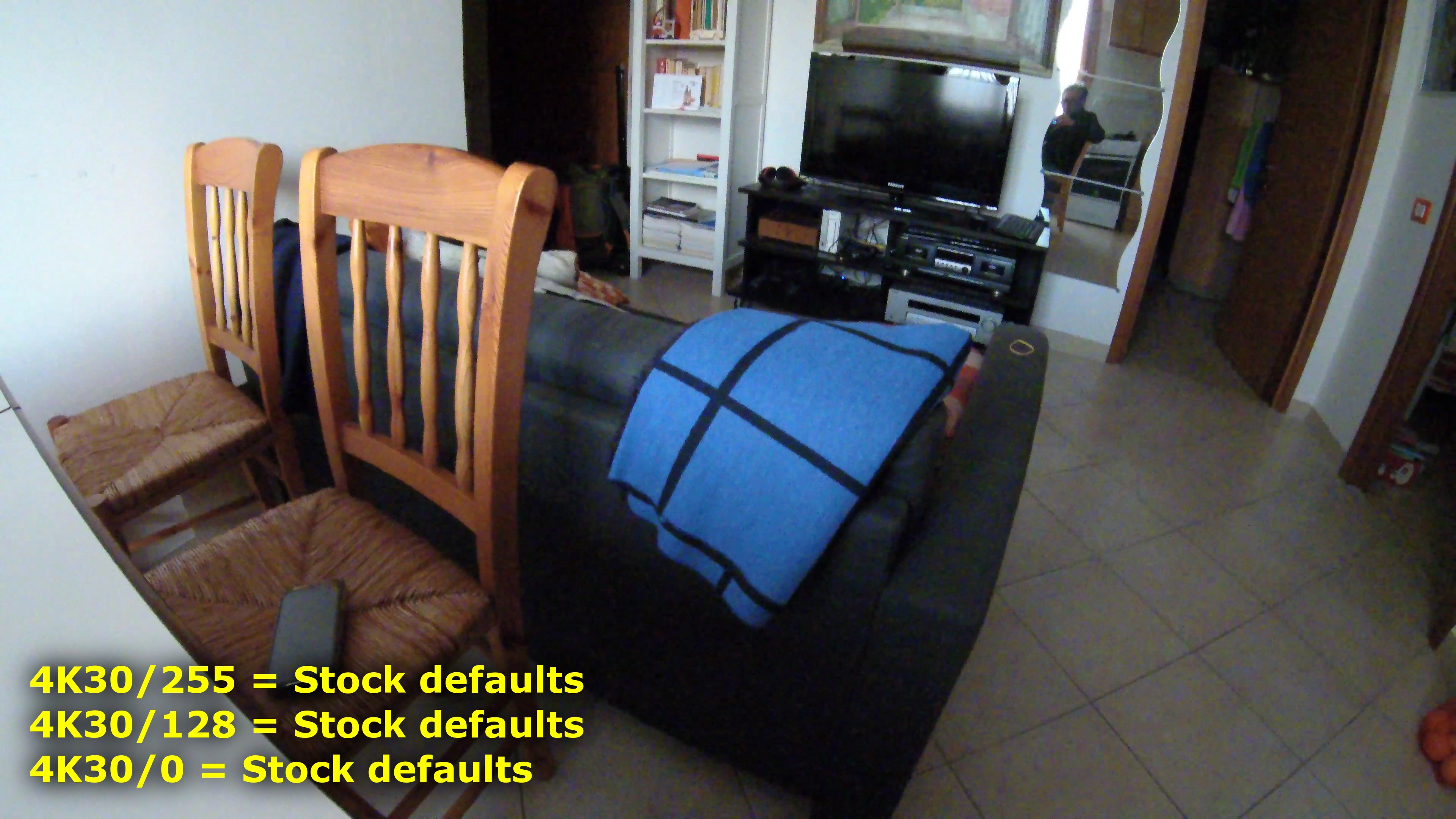
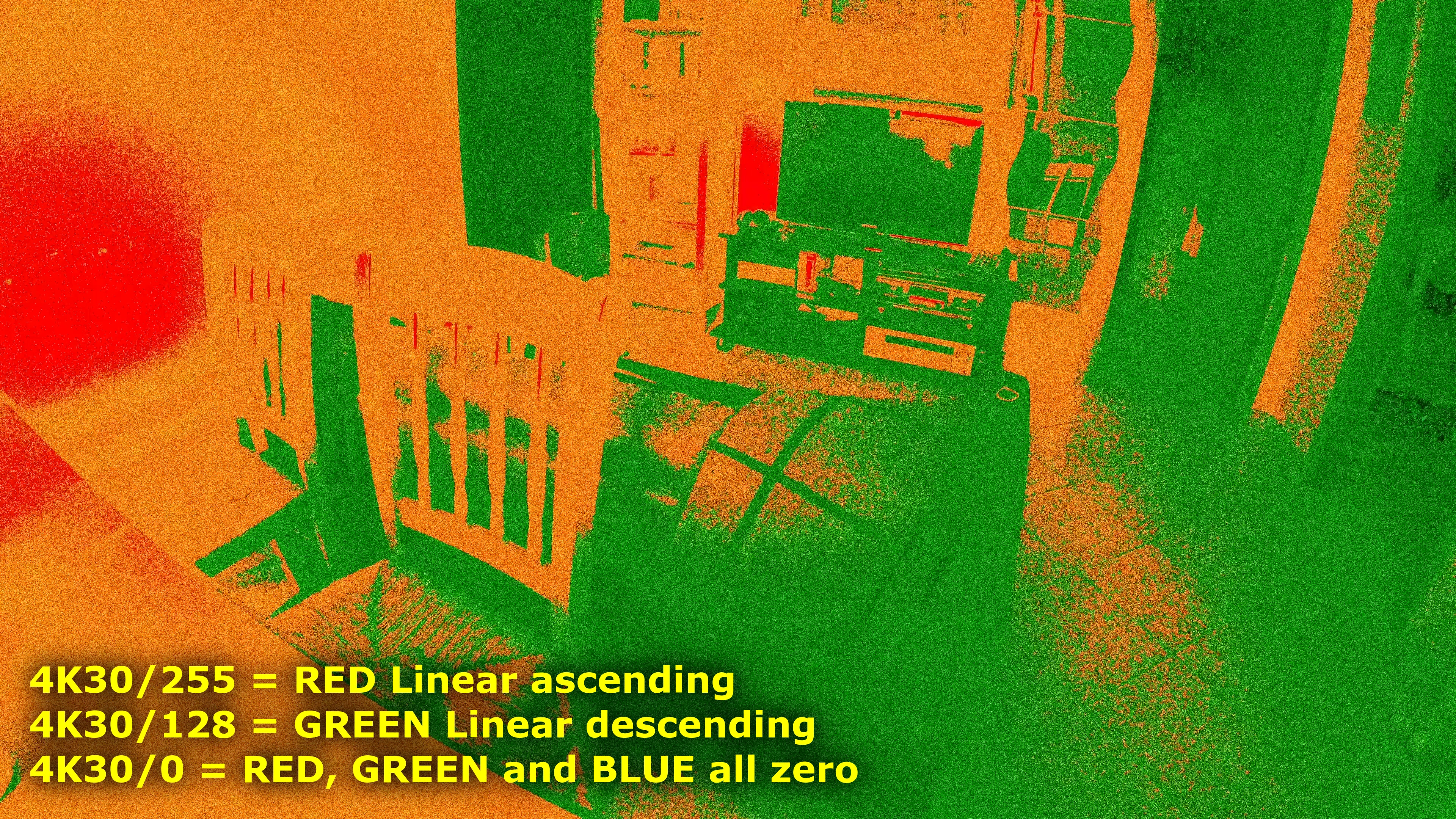
Finally I tried another border case, where the */255 group is all zero and the */128 group is linear. Two different tests demonstrate that the */0 group does not play any role in the processing.
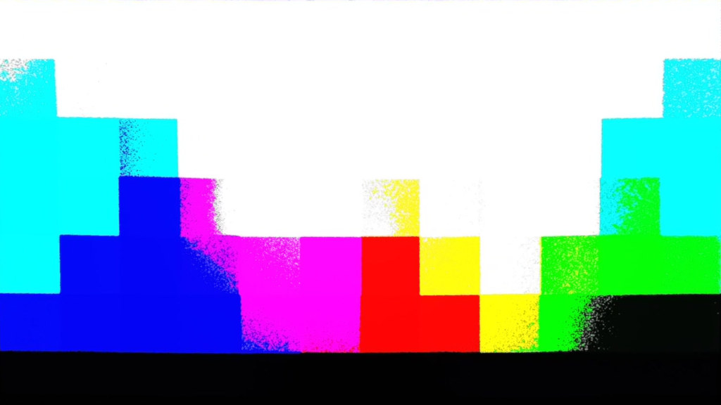
We will have expected that the brightest part of the image become almost black, but instead we got a strange effect, where colors become somewhat negative: you can see the green part at the center of the image (red on the original image) and the red stripe at the top (which is white on the original image, but it can be actually be sensed as light cyan by the camera).

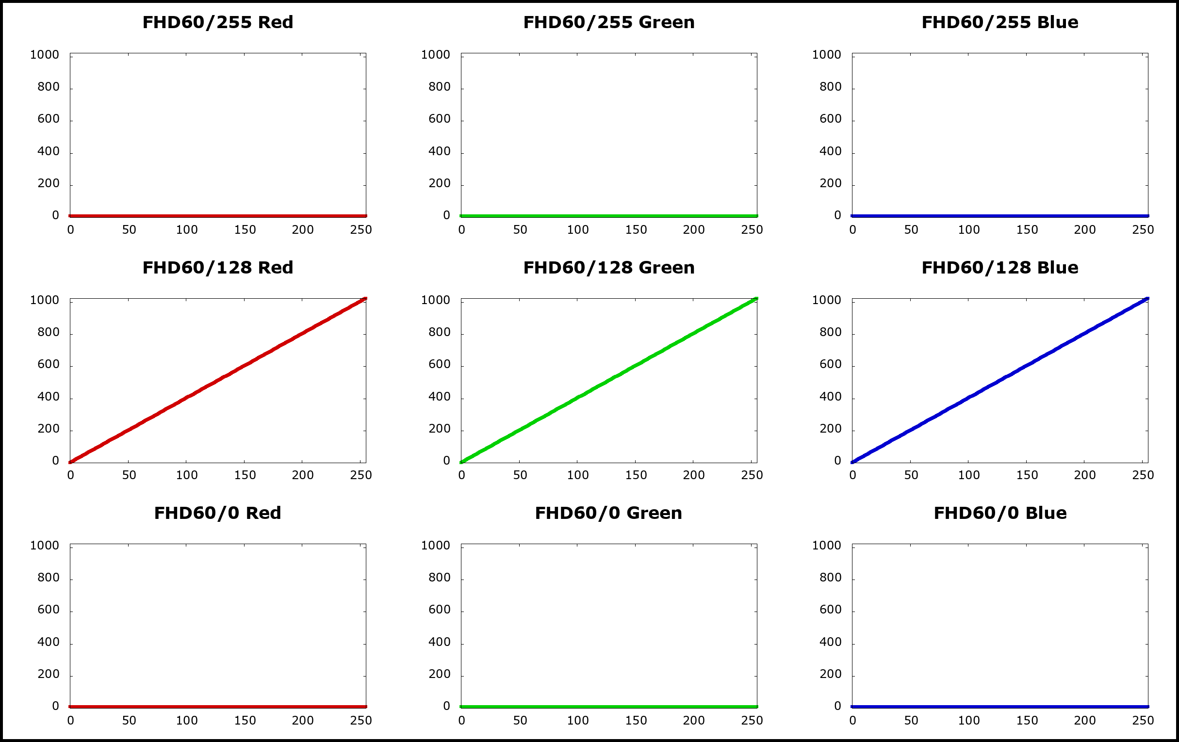
Gamma curves */0 are not used
It was supposed that the three groups 4K30/255, 4K30/128 and 4K30/0 are used with interpolation at different light levels (highlight, midtones and shadows), but it seems not to be true. Making several tests it turned out that groups 4K30/255 and 4K30/128 are actually used with interpolation for highlights and shadows, but the 4K30/0 is not used at all. It is not clear if there is a firmware bug or if the theory is non understud, but to the practical effect you can ajust the other two group and leave the 4K30/0 untouched (or make it a straight ascending line, just to be safe) because the effect is not noticeable.
We tried also groups 720@240/* (tables found in file adj_video_default_04_Imx377), obtaining the same results, so we deduce that the rule applies to all the adj_video_default_*_Imx377 files: the */0 curves have no effects at all.
In the following frames you can see how the 4K30/255 and 4K30/128 groups produces the expected results, whereas the 4K30/0 does not have any effect. The definitive proof should be that zeroing groups 4K30/255 and 4K30/128 and leaving at default values the group 4K30/0, produces a perfect black frame.


Chroma curves
It is possibile to apply a transformation to the chrominance of the images, i.e. the color saturation. The Ambarella processor applies chroma transformations probably at the same stage of gamma correction, as the transformation tables are stored into the same files.
BitrateEditor exposes three chroma tables: 4K30/255, 4K30/128 and 4K30/0; theirs content affects videos filmed in 4K at 24 and 30 FPS. Videos taken at other resolutions (Ultra, 720, 1080, 1440 and 2.7K) are affected by others tables that should be added to BitrateEditor, see issue #8.
Also photos have their chroma tables contained into adj_still_default_00_Imx377 and adj_hiso_still_default_00_Imx377.
| Tables | Contained in file | Used for video modes |
|---|---|---|
| 4K30/* | adj_video_default_00_Imx377, offset 0x74F4 | 4K@(25,30) |
| 4K60/* | adj_video_default_01_Imx377, offset 0x74F4 | 4K@(50,60) |
| 1080/* | adj_video_default_02_Imx377, offset 0x74F4 | 4K@24 4K-Ultra@(24,30) 2.7K@(24,25,30,50,60) 2560×1440@(24,25,30,50,60) 1920×1080@(24,25,30,50,60) 1920×1080-Ultra@(30,60) Touch screen menu |
| FHD120/* | adj_video_default_03_Imx377, offset 0x74F4 | 1920×1080@120 |
| 720/* | adj_video_default_04_Imx377, offset 0x74F4 | 1280×720@240 |
| Tables | Contained in file | Used for photo modes |
| Photo/* | adj_still_default_00_Imx377, offset 0xA63C | Photo 100,200,400 Photo Lapse 100,200,400 Burst Mode 100,200,400,800,1600,3200,64000 |
| Photo-Hi-ISO/* | adj_hiso_still_default_00_Imx377, offset 0xA63C | Photo 800,1600,3200,6400 Photo Lapse 800,1600,3200,6400 |
Each chroma curve is defined by 128 points that map to a chrominance value ranging from 0 to 2048. On the X axis there is the brightness of the image pixels, on the Y axis there is the chroma correction factor to be applied. A value of zero means to remove all the chroma information, thus producing a grayscale image; the maximum value of 2048 instead means an over-saturated color. The median natural value should be 1024.
In the following image you can see how BitrateEditor shows the chroma 4K30/128 table. All values are equal to 1024, thus resulting into a stright line:

BitrateEditor can show the tables also as curves, here there are the ones provided by the original SJCAM firmware 1.3.2:


The three curves are applied by stretching the full range over the full brightness range of the image, i.e. the leftmost point of the curve applies to the darkest points of the image, the rightmost point of the curve applies to the brightest points of the image. The three curves are combined together, probably each one is weighed upon the overall exposition of the image. It seems that the 4K30/128 is the most effective for evenly exposed images, so it is the most effective correction on the overall result. The curve 4K30/0 weighs more when the image is overexposed and the curve 4K30/255 weighs more when the image is underexposed (generally the effect of the last one is barely noticeable). Probably, after applying the weigh calculated on exposure, the three values are added together and trimmed to 2048.
Changes made on tables 4K30/* will be written by BitrateEditor into the file adj_video_default_00_Imx377, changes on tables FHD30/* should go instead into adj_video_default_02_Imx377.
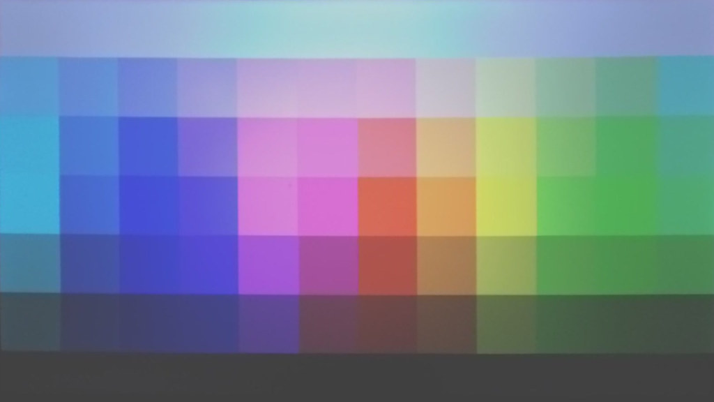
Chroma curves examples
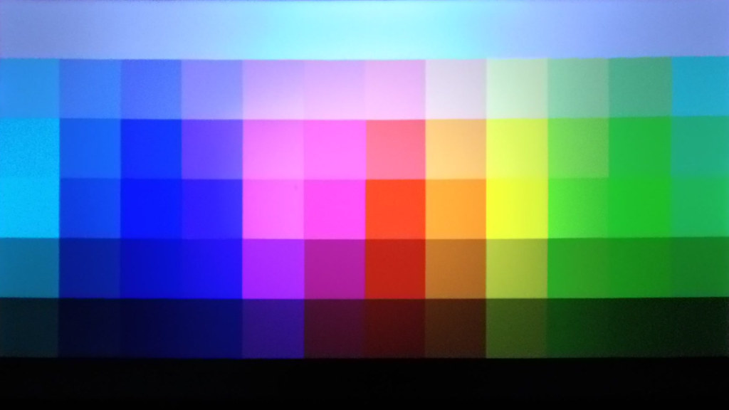
In the following images you can have an idea on how the three chroma curves influence the color saturation of the image. For each test we prepared the three graphs (4K30/255, 4K30/128 and 4K30/0) as a different patterns of a square wave. Then we filmed a reference image using different exposition values.
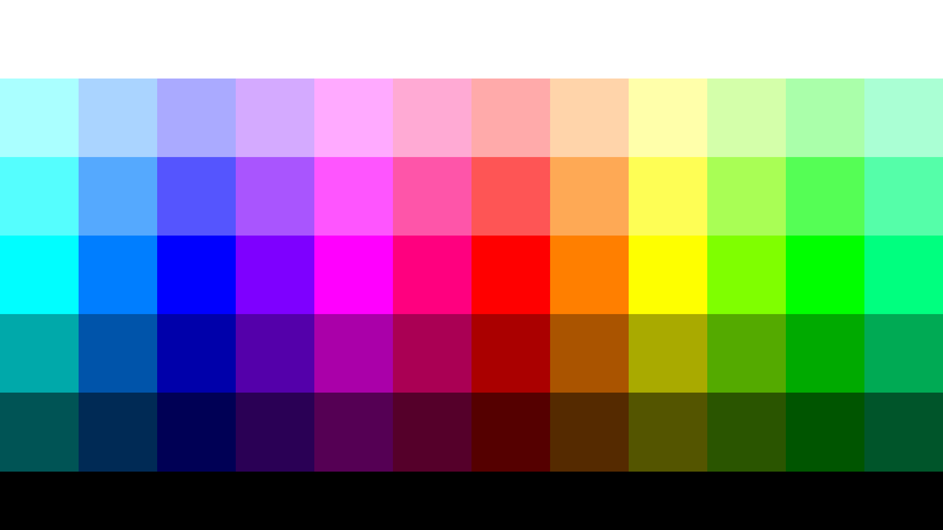
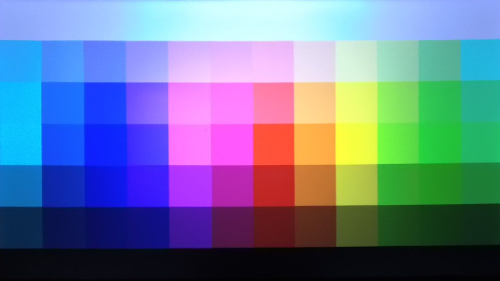
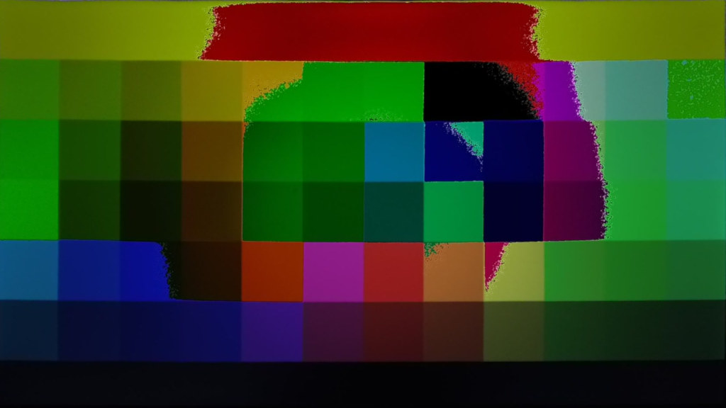
Here you are the reference image; a gradient of the full RGB palette created with a Python script:

Curve 4K30/255
We tried to understand when the 4K30/255 curve is used. It turned out that it is used only for underexposed images: only using an EV -2.0 it was possibile to barely view the effect of the square tooth at the center of the graph:


Using an exposition of EV -1.0 or higher, no chrominance is added at all. Some mild effect is visible at EV -2.0, despite the chroma graph teeth were set to the maximum value of 2048. In the darker part of the image the effect is not noticeable; the first tooth on the left produces almost no effect. Also the third tooth on the right does not produces any noticeable effect. Only the central narrow tooth produces a narrow band of color. If the tooth instead expands from the center to the right (last image), the colored area expands from the center towards the upper brightest part.
So the maximum effect of the 4K30/255 curve is at EV -2.0, but is very mild even if the curve is all set to 2048 max value (which is the SJ8 Pro defualt):

Curve 4K30/128
The curve 4K30/128 is the most effective; its effect is visible very well from EV -2.0 to EV +2.0:


Curve 4K30/0
The curve 4K30/0 is effective, using the maximum value of 2048, starting from EV 0.0 and above:


Mixing the curves
The first example shows the effect of creating some disjointed theet on the three curves; each tooth is set at the maximum value of 2048. Actually the single tooth of the curve 4k30/255 produces almos no visble effect, you can see only three narrow bands of colors corresponding to teeth on curves 4K30/128 and 4K30/0:

The last example is used to show how curves are mixed together. In this case a wide teeth on curve 4K30/128 is mixed with a narrow teeth on curve 4K30/0. Each teeth is set to 1024 (half of the maximum), so taht the more satured color band on the overlapping region can be apreciated.

AGC and digital gain
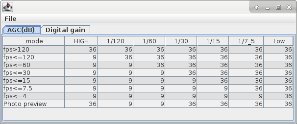
Automatic Gain Control
White balance presets
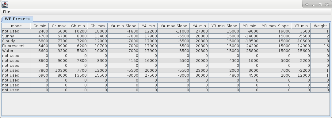
 : It is not know how this table works. It seems that labels are wrong: YA_min and YB_min are repeated twice, may be they are YA_max and YB_max.
White balance is probably applied as a series of linear transformations to the four raw values captured by te Bayer filter sensor. The four channels are Red, Green-on-red, Blue and Green-on-blue, each transformation consists of a multiplier coefficient (slope) and an offset.
| Gr | Green on Red |
|---|---|
| Gb | Green on Blue |
| Ya | Y channel value of target image? |
| Yb | Y channel value of reference image? |
3D LUT tables
There are some 16x16x16 3D LUTs tables for color grading inside the files VideoCc[0-4]_Imx377 and StillCc[0-4]_Imx377 (contained in section #3 of the firmware file). See this post on 4pda.to (in Russian) and this one about the file format used.
Using a Python script I extracted the five LUTs from the VideoCc* files and created a sequence of images from them:


It remains to be seen when such tables are used. The files StillCc* contain the same LUT tables.
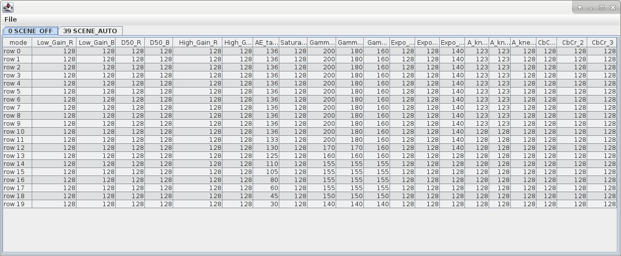
Scenes
Sharpness
The author is adding support for editing sharpness tables in BitrateEditor: see his post: таблиц резкости.
Audio files
Partition #3 contains some .pcm audio files which are used at power-on, power-off, etc. The following files exist:
- img_48k.pcm - Photo shutter noise.
- optone_48k.pcm - Bell.
- power_off_48k.pcm - Power-on sound.
- power_on_48k.pcm - Power-off sound.
They are headerless audio files, but you can convert them to wav using SoX, a command line tool to manipulate audio files.
sox -r 48k -e signed-integer -b 16 -L -c 1 -t raw power_off_48k.pcm power_off_48k.wav
The following table explains the SoX command line options used:
| -r, –rate RATE[k] | Sample rate. |
|---|---|
| -e ENCODING, –encoding ENCODING | PCM data stored as signed (two’s complement) integers. |
| -b BITS, –bits BITS | The number of bits in each encoded sample. |
| -L, –endian little | The byte-order of the audio data. |
| -c CHANNELS, –channels CHANNELS | The number of audio channels in the audio file. |
| -t, –type FILE-TYPE | Gives the type of the headerless audio file. |
Ambarella imaging pipeline
The following image is leaked from the Ambarella A12 SDK:
