Table of Contents
Honda NTV650 Revere - Carburetor
The Honda NTV650 Revere mounts two Keihin vacuum piston carburetors. When servicing the carburetors, it must be kept in mind that in addition to the vacuum piston diaphragm, there is also a small diaphragm that operates the air cut-off valve.
Here it is my experience in replacing the diaphragms and some information on the little-known air cut-off valve.
Replacing the diaphragms
Replacing the diaphragms at 100.000 and 200.000 km
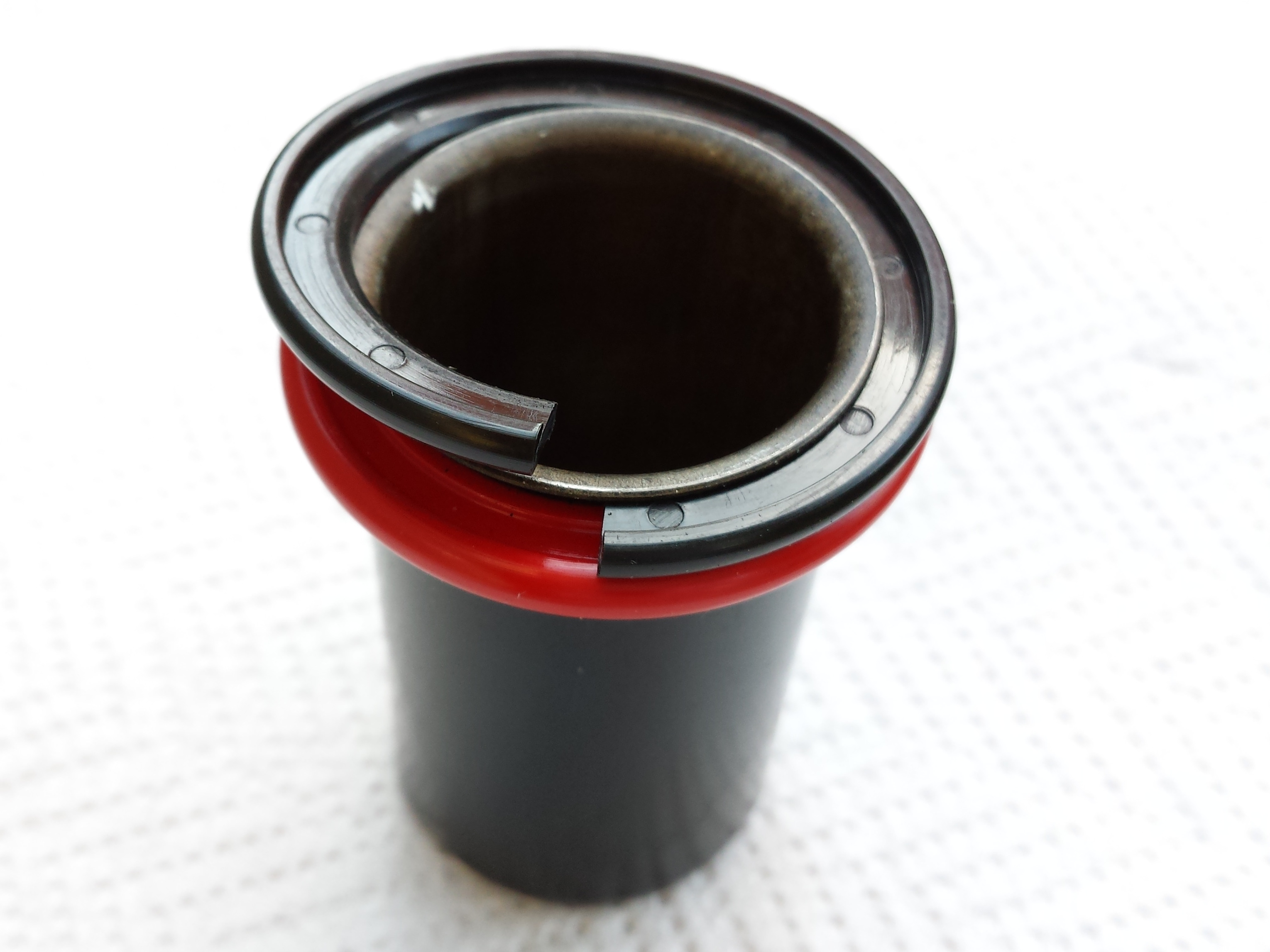
I replaced the complete vacuum cylinders with diaphragms the first time after 12 years, at 113,000 km. After another 12 years (24 years and 201,000 km in total) the diaphragms were again to be changed as shown in the photo:

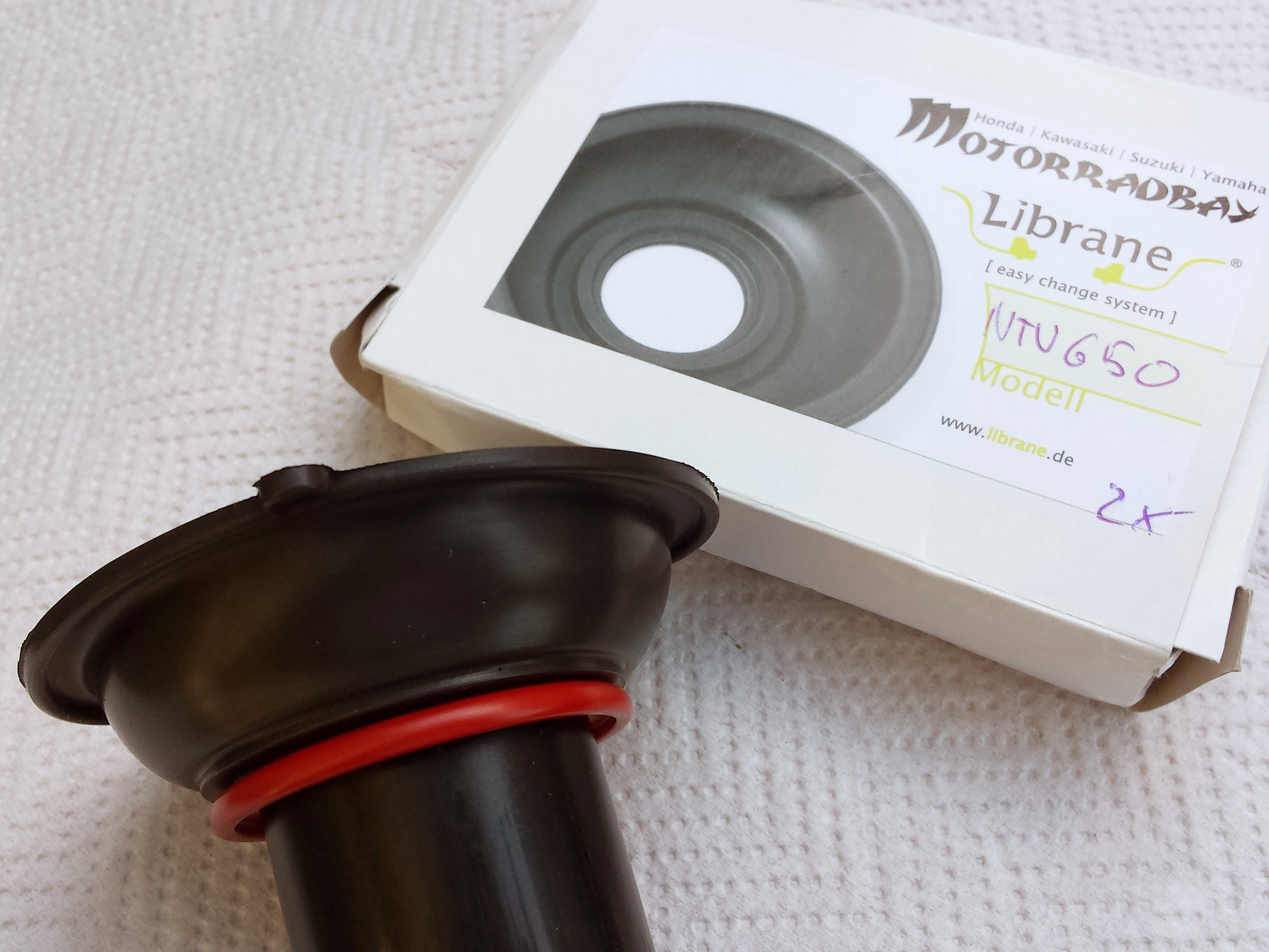
Unfortunately, mother Honda no longer produces the spare part (code 16112MN8014)! There are at least three types of non-original membranes adaptable to the NTV650, which differ in the way they are installed. One type requires cutting the upper plastic ring (the black one) which is then put back in place and glued. A second type requires that the black ring be removed and thrown away (it is the Librane model seen in the following photos), the replacement membrane is held in place with cyanoacrylate glue. The glue supplied is gel type, resistant to petrol and high temperatures. Finally, there is a model that must be installed like the original, inserting it in the space between the red and black rings.
The following photos show the installation of a Librane type membrane, but I definitely prefer the type that fits exactly like the original; inserting the replacement diaphragm into the slot using a credit card is quite simple and does not require permanently modifying the piston.
Before removing the old membrane mark the point on the piston that corresponds to the membrane slot, because the new one will have to be positioned at exactly the same angle. The black ring can be cut with a cutter and removed. The groove can be cleaned and degreased with synthetic thinner. Be careful to spread a very thin layer of glue, so that the membrane enters well into the housing without encountering any thickness.
As soon as they were mounted, the result seemed good: the precision and sensitivity of the throttle was significantly improved compared to the old cracked membranes. In a few months I will check the actual seal of the membrane and especially of the glue. The one supplied reports among its characteristics a maximum operating temperature of 80 °C. Probably the Loctite 454 has better characteristics.
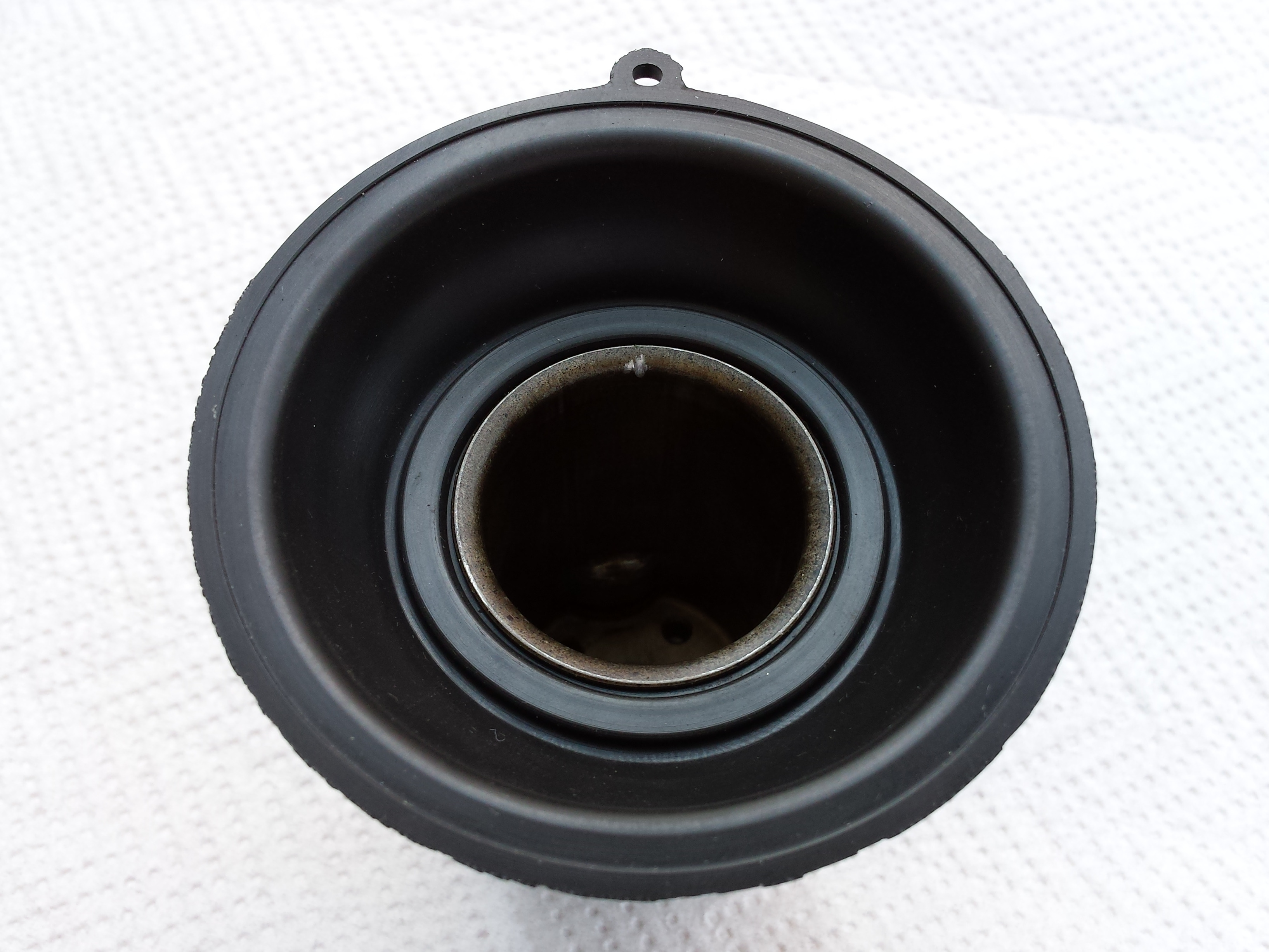
In the following picture you can see the mounting position of the diaphragm. You can see the angle with the vertical axis measuerd on the top cover and a view of the piston from below:


Jets and pilot screw

 The main jets are different sizes in the front and rear cylinder carburetors.
| Carburetor | Main Jet | Slow Jet |
|---|---|---|
| Right (front cylinder) | #140 | #42 |
| Left (rear cylinder) | #135 | #42 |
The pilot screw is used to regulate the air-fuel ratio for the engine idle speed; turinig it counterclockwise enrich the mixture (more gasoline). The default setting is 2 turns counterclockwise from the full-seated position.
The factory settings are likely to be for a very lean mixture at idle, which is also why the cut-off valve is needed. This setup is required to meet stringent pollution regulations. It may be that the best idle performance is achieved with a richer mixture (pilot screw turned out more than two turns). A richer idle also reduces the possibility of afterburn (exhaust popping) when the throttle is released.
Fuel and breather pipes placement
In the following photos you can see how the fuel line and the breather tube are positioned around the carburetors.


The above is how I found the tubes in my 1988 NTV650J Revere, but I have also a 1989 NTV650K that has the breather tube going to the left side, in a mirror-like way. In this case the binder bracket on the right top cover can accommodate the choke cable.


Carburetors synchronization
Remove tha tank and connect two vacuum gauges to the cylinders intakes using two joints plugs (Honda part 16214-MB0-000). Provide the fuel in some way, warm up the engine and adjust the idle speed (1100 +/- 100 rpm). The difference in vacuum reading should be 40 mm Hg or less.
If necessary, synchronize to the specification by turning the synchronization adjusting screw: screwing-in by turning clockwise will increase the idle of the rear cylinder.


The air cut off valve
![]() The Keihin carburetors on the NTV650 Revere feature the so-called air cut-off valve, a device that serves to enrich the air-fuel mixture when the throttle is closed and the engine has not yet slowed down (for example when using engine braking on a downhill run). In this condition, the cylinder sucks in with greater force than at normal idle, the idle jet therefore supplies a mixture that is too lean and the afterburn phenomenon occurs. Afterburn is the popping of the engine caused by a mixture that is too lean and cannot ignite in the combustion chamber. The unburned gasoline passes into the exhaust pipe and here, due to the high temperature, it ignites, producing the annoying explosions.
The Keihin carburetors on the NTV650 Revere feature the so-called air cut-off valve, a device that serves to enrich the air-fuel mixture when the throttle is closed and the engine has not yet slowed down (for example when using engine braking on a downhill run). In this condition, the cylinder sucks in with greater force than at normal idle, the idle jet therefore supplies a mixture that is too lean and the afterburn phenomenon occurs. Afterburn is the popping of the engine caused by a mixture that is too lean and cannot ignite in the combustion chamber. The unburned gasoline passes into the exhaust pipe and here, due to the high temperature, it ignites, producing the annoying explosions.
The cut-off valve circuit is a duct that complements the idle circuit and contributes for its own part to the air-fuel mixture for the correct idle functioning. The difference is that in this circuit the air duct can be closed, temporarily creating a greater supply of gasoline. The cut-off valve is operated by a membrane connected to the intake manifold: when the vacuum is very high (high rotation speed and closed throttle valve) the membrane closes the cut-off air duct; the result is a richer mixture that avoids afterburn. When the engine speed drops, the vacuum becomes lower and the cut-off valve returns to its rest position; the idle circuit is then returned to normal condition.
![]() I carburatori Keihin della NTV650 Revere montano la cosiddetta valvola air cut-off, si tratta di un dispositivo che serve ad arricchire la miscela aria-benzina quando si chiude il comando del gas e il motore non ha ancora diminuito il numero di giri (ad esempio quando si usa il freno motore in discesa). In tale condizione il cilindro aspira con una forza maggiore rispetto al normale regime del minimo, il getto del minimo fornisce quindi una miscela troppo magra e si ha il fenomeno dell'afterburn. L'aferburn è lo scoppiettio del motore causato da una miscela troppo magra che non riesce ad incendiarsi nella camera di scoppio. La benzina incombusta passa nello scarico e qui, a causa dell'alta temperatura, si incendia producendo i fastidiosi scoppi.
I carburatori Keihin della NTV650 Revere montano la cosiddetta valvola air cut-off, si tratta di un dispositivo che serve ad arricchire la miscela aria-benzina quando si chiude il comando del gas e il motore non ha ancora diminuito il numero di giri (ad esempio quando si usa il freno motore in discesa). In tale condizione il cilindro aspira con una forza maggiore rispetto al normale regime del minimo, il getto del minimo fornisce quindi una miscela troppo magra e si ha il fenomeno dell'afterburn. L'aferburn è lo scoppiettio del motore causato da una miscela troppo magra che non riesce ad incendiarsi nella camera di scoppio. La benzina incombusta passa nello scarico e qui, a causa dell'alta temperatura, si incendia producendo i fastidiosi scoppi.
Il circuito della valvola cut-off è un condotto complementare al circuito del minimo e contribuisce con una sua parte alla miscela aria-benzina per il corretto funzionamento del minimo. La differenza è che in tale circuito il condotto dell'aria può essere chiuso creando temporaneamente un maggiore apporto di benzina. La valvola cut-off viene azionata da una membrana collegata al condotto di aspirazione: quando la depressione è molto alta (alti regimi di rotazione e valvola a farfalla chiusa) la membrana fa chiudere il condotto dell'aria cut-off; il risultato è una miscela più ricca che evita l'afterburn. Quando il motore scende di giri la depressione diventa minore e la valvola cut-off torna nella posizione di riposo; il circuito del minimo viene quindi riportato alla condizione normale.
Repair kits
You can find several carburator repair kits on the net, many of them are no-branded, mainly Chinese production. What you want to replace mostly will be the float chamber gasket and the valve needle, whose rubber may have hardened and deformed. It is nice if the kit contains also the other o-rings.

 I found that several kits have low quality and/or low design parts, especially the float chamber gasket may be too thin or does not perfectly fit the cave. A nice exception is the kit from Keyster, a Japanese company specializing in carburetor restoration kits. I purchased the KH-1348 kit specifically produced for the Honda NTV650 Revere 1988-1990 and it turned out to be of excellent quality. The kit contains:
- 2 x Gasket chamber
- 2 x Valve seat with washer, filter and needle
- 2 x Screw air with spring, O-ring and washer
- 2 x Drain screw with O-ring
- 1 x Jet main #140
- 1 x Jet main #135
- 2 x Jet slow #42

The kit does not contain the stem holding the main jet nor the little oval gasket of the air cut-off valve, but I was particularly pleased with the float chamber gasket: the shape and size are perfectly similar to the original.
It seems that also the Keyster kit K-976EK is compatibile with the NTV650 Revere, it contains fewer parts, but it contains the same rubber parts as the KH-1348 kit, plus the oval O-ring of the air cut-off valve. Another kit from Keyster is the K139 (also labeled NTMOR-007G), which includes only the float chamber gasket.
Problem with the Keyster valve seat
After overhauling the carburetors with the Keyster kit, I had a problem with the float valve seat. Even though I had adjusted the float level according to the manual (9.2 mm), after driving for a few kilometers, the fuel began dripping from the carburetor vent tube. Evidently the valve wasn't closing, and the float chamber was overfilling.
To confirm that the fuel level was the problem, I connected two clear rubber hoses to the carburetor drains. The hoses were then bent upward, above the fuel cap. By loosening the drain screws of the carburetors, you can see the fuel level in the hose, which will be equal to the level in the float chamber. After a few kilometers of driving, I confirmed that the level in one of the two carburetors had risen several centimeters and was now reaching the breather pipe.

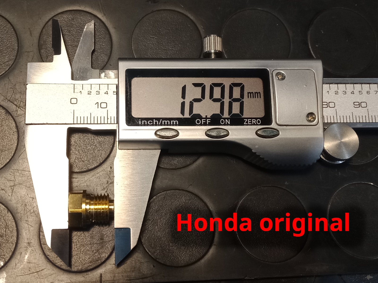
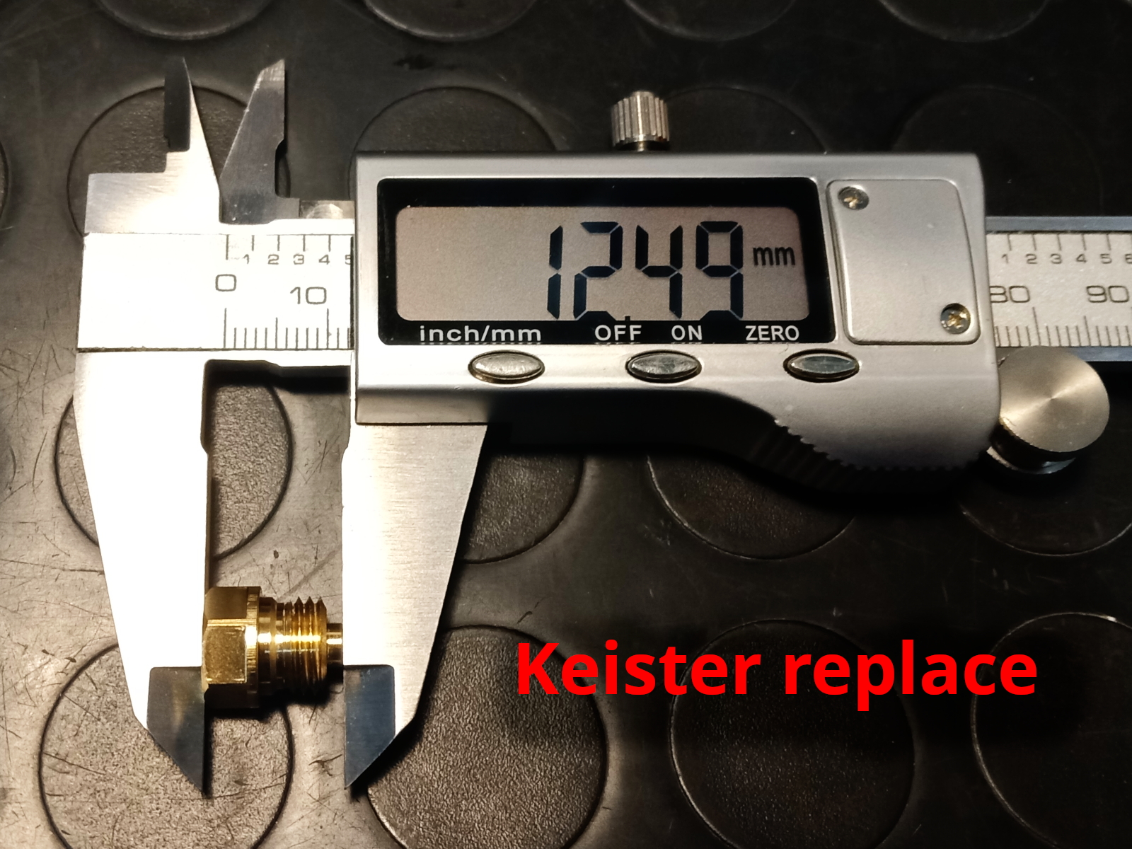
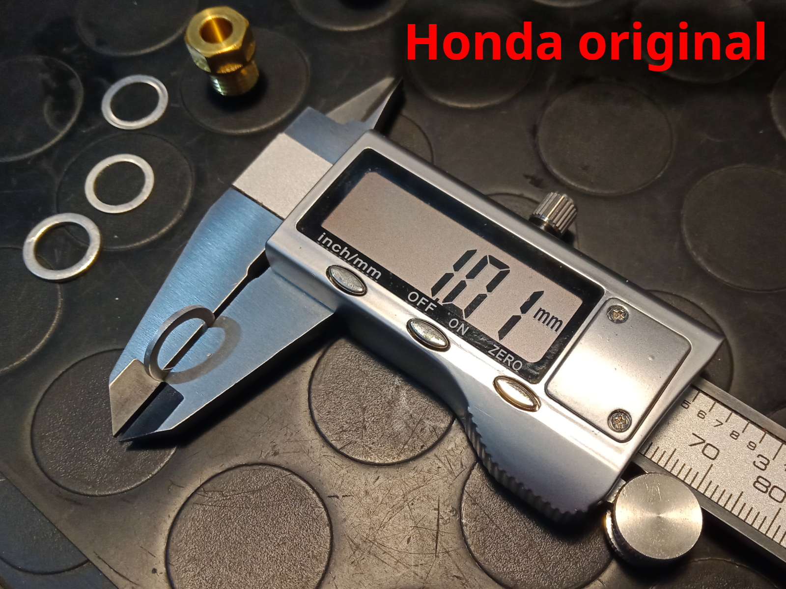
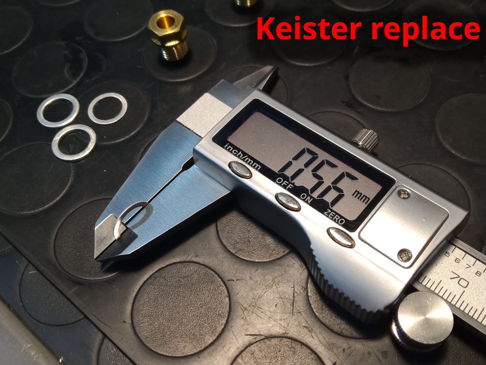
When I removed the carburetor, I noticed that the Keyster replacement had different dimensions than the original, both the valve seat and the washer. To be safe, I reassembled the originals, and the problem was solved.
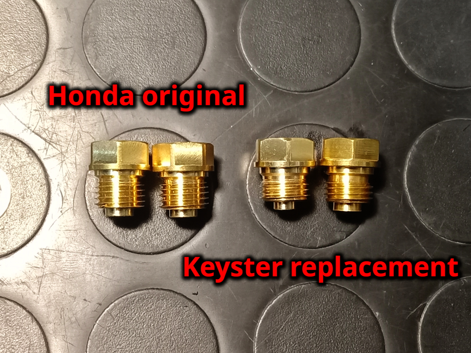
The Keyster replacement for the pilot screw is identical for the inside part. The external part is short and is intended to be closed with a cap, as is mandatory in some countries due to environmental pollution regulations.


Do not use red paste gasket sealant!
I once installed a float chamber gasket whose size I didn't trust, so I added some red gasket sealant, by Würth. The result was disastrous: after less than a year and about 2000 km, the red paste dissolved in the fuel and formed a sludge in the carburetor float chamber. Naturally, the bike began to have idle problems and backfiring. Cleaning the inside of the carburetor was a pain, luckily nitro thinner seems to dissolve this red sludge.


Web References
- The air cut valve (local PDF version)
- Keihin Idle Circuit White Paper (Macromedia Flash file, local PDF conversion)
- Air cut off valve explained (video, in English)
- Come funziona la air cut-off valve (video, in Italian)